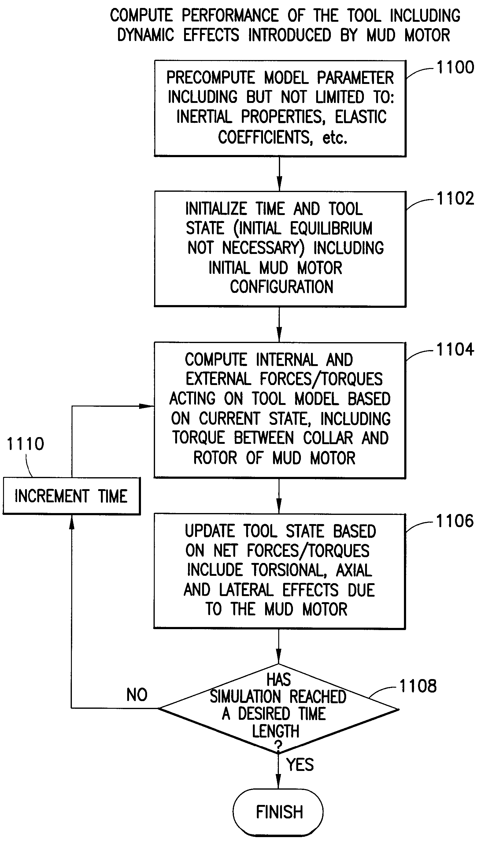
Modeling Vibration Effects Introduced By Mud Motor
a technology of vibration effects and motors, applied in the field of drilling boreholes, can solve the problems of little work on modeling the specific effects caused by the use of mud motors, no treatment of transient aspects of torque and force being transmitted between the stator and the rotor, and significant and complex changes in the dynamic behavior of the tool, so as to enhance the drilling effect of the drilling tool
- Summary
- Abstract
- Description
- Claims
- Application Information
AI Technical Summary
Benefits of technology
Problems solved by technology
Method used
Image

Examples
Embodiment Construction
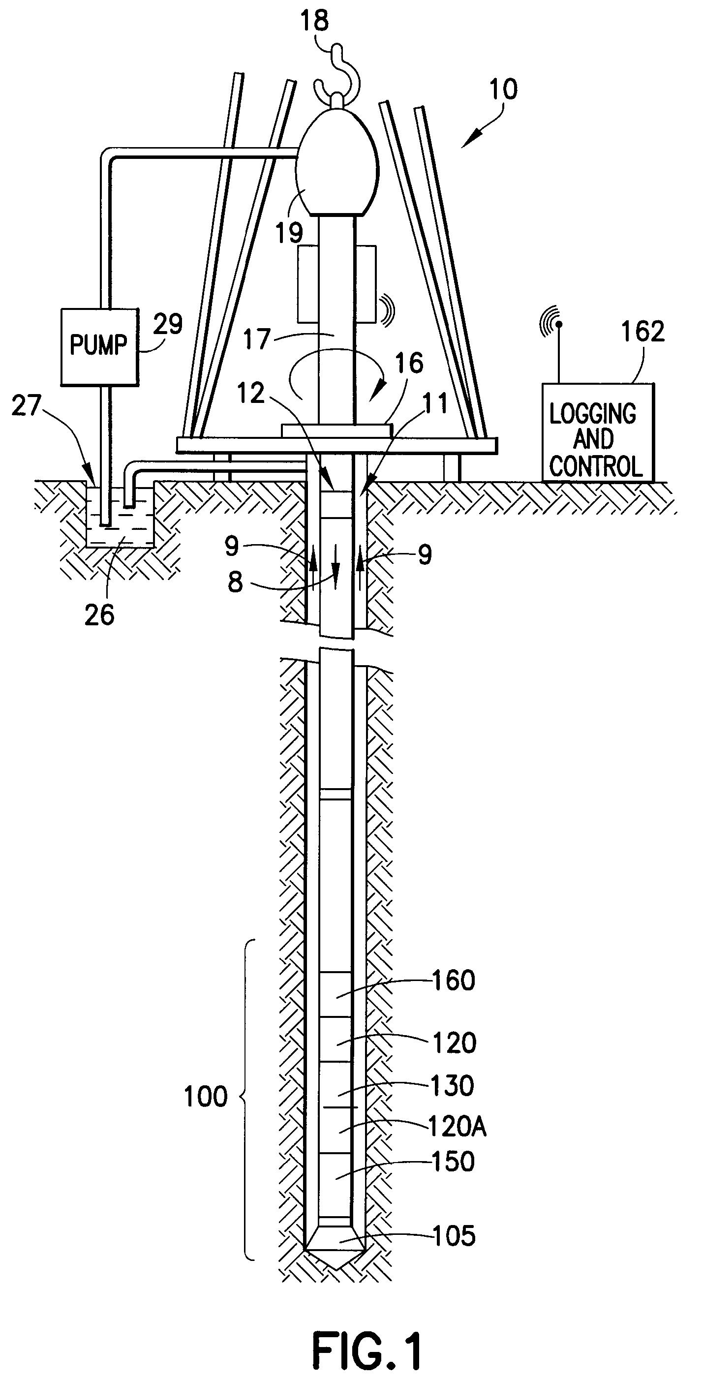
[0020]FIG. 1 illustrates a wellsite system in which the present invention can be employed. The wellsite can be onshore or offshore. In this exemplary system, a borehole (11) is formed in subsurface formations by rotary drilling in a manner that is well known. Embodiments of the invention can also use directional drilling, as will be described hereinafter.
[0021]A drill string (12) is suspended within the borehole (11) and has a bottom hole assembly (100) which includes a drill bit (105) at its lower end. The surface system includes platform and derrick assembly (10) positioned over the borehole (11), the assembly (10) including a rotary table (16), kelly (17), hook (18) and rotary swivel (19). The drill string (12) is rotated by the rotary table (16), energized by means not shown, which engages the kelly (17) at the upper end of the drill string. The drill string (12) is suspended from a hook (18), attached to a traveling block (also not shown), through the kelly (17) and a rotary sw...
PUM
 Abstract
Description
Claims
Application Information