Stopper structure and production method therefor

Inactive Publication Date: 2010-07-01
KROSAKI HARIMA CORP
View PDF3 Cites 2 Cited by
  • Summary
  • Abstract
  • Description
  • Claims
  • Application Information

AI Technical Summary

Benefits of technology

[0041]1. Loosening of the joining between the refractory stopper and the shaft rod during use can be prevented to reduce a risk of breakage of the stopper structure due to a moment, such as bending moment, applied to a part of the stopper member in a concentrated manner;
[0043]3. An operation which is complicated / laborious, and unstable in accuracy of joining between the refractory stopper and the shaft rod, for example, an operation of installing a member, such as a joining member between the refractory stopper and the shaft rod, onto the refractory stopper using mortar, can be omitted to improve operating efficiency and enhance the accuracy of joining between the refractory stopper and the shaft rod;
[0045]5. In a conventional stopper structure, joining between a refractory stopper and a shaft rod is loosened during use, and thereby only a fixing (fastening) mechanism capable of coping with a retorquing operation, such as thread-based joining, can be employed. In the present invention, the joining between the refractory stopper and the shaft rod is not loosened during use. This allows a fixing (fastening) mechanism using a fingertip connector mechanism to be employed. Thus, the shaft rod can be fixed (fastened) to the refractory stopper in conjunction with an operation of connecting two shaft rod segments together in a simple manner. This makes it possible to improve laborsaving and operating efficiency, as compared with a conventional technique requiring a plurality of operations, while reducing differences among individuals in the fixing (fastening) operation and the retorquing operation, to allow a casting operation to be stably performed using the stopper structure; and

Problems solved by technology

Thus, thermal expansion of the metal is likely to cause breakage of a portion of the refractory stopper surrounding the metal.
However, the use of this type of bonding material is likely to cause a problem, such as loosening between the metal shaft rod and the refractory stopper, due to deformation or collapse of the bonding material.
Consequently, stress concentration occurs in a local area of the refractory stopper to cause a risk of breakage of the refractory stopper.
Moreover, when the stopper structure is designed to allow gas to pass therethrough, a risk of gas leakage and sucking of external air will also increase.
In reality, the refractory material cannot be subjected to burning while setting a part of the metal shaft rod within the refractory material, because thermal expansion of the metal shaft rod causes breakage of a portion of the refractory material surrounding the metal shaft rod.
Although a gap or a cushioning material may be provided around the metal shaft rod to absorb the thermal expansion, the gap or cushioning material precludes a possibility of obtaining sufficient fixing (fastening) and contact.
Thus, even if the refractory stopper is only slightly inclined, a large moment is applied to the support region, and stress concentration is highly likely to occur in a local area of the joining portion to cause breakage of the refractory stopper and other associated member.
Thus, in addition to complexity and laboriousness in the shaft rod mounting operation in a casting workplace, high mounting accuracy is required, particularly, for preventing gas leakage in the stopper structure designed to allow gas to pass therethrough.
This imposes a heavy burden on a user.
Moreover, even after the mounting operation having such a heavy burden, the fixed (fastened) state between the shaft rod and the refractory stopper has to be constantly corrected by a retorquing operation or the like, because loosening between the shaft rod and the refractory stopper occurs due to thermal expansion of the shaft rod and continuous action of varying external force, such as vibration, during casting operation.
Even if the mounting operation is carefully performed with a high degree of accuracy, and the correction operation, such as retorquing operation, is intermittently performed, there still remains a problem of being unable to completely avoid breakage of the refractory stopper and the bonding material, and gas leakage, in the upper end region of the refractory stopper.
However, in the stopper structure designed to mount the cylindrical-shaped, metal, shaft-rod joining member inside the refractory stopper 2, due to thermal expansion of the metal shaft rod 1 along with an increase in temperature thereof during use, the metal, shaft-rod joining member 14 embedded in the refractory stopper 2 is likely to break a portion of the refractory stopper surrounding the shaft-rod joining member 14.
Moreover, due to elongation of a vertical length of the shaft rod 1, loosening (gap) between the shaft rod 1 and the refractory stopper 2 occurs to cause instability in fixed (fastened) state between the shaft rod 1 and the refractory stopper 2, and difficulty in ensuring gas-tightness therebetween, which leads to gas leakage.
Furthermore, a contact region between the shaft rod 1 and the refractory stopper 2 locally occurs, and triggers a higher risk of breakage of the refractory stopper.
However, even if such a shaft-rod joining member having relatively small thermal expansion is pre-mounted, it is unable to improve the problems that the shaft-rod joining member is pressingly broken due to thermal expansion of the metal shaft rod joined thereto, and loosening between the shaft rod and the refractory stopper occurs due to elongation of a vertical length of the shaft rod, to cause instability in fixed (fastened) state between the shaft rod and the refractory stopper, and difficulty in ensuring gas-tightness therebetween, which leads to gas leakage.
Nevertheless, it is difficult to completely eliminate the gap or loosening, because of the manual and intermittent operation.
This is one of the problems in casting operation.

Method used


Image

  • Stopper structure and production method therefor
  • Stopper structure and production method therefor
  • Stopper structure and production method therefor

Examples


first embodiment

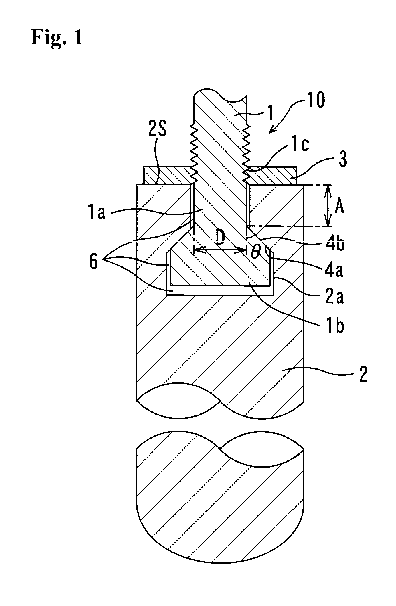
[0081]FIG. 1 is a sectional view showing a stopper structure according to a first embodiment of the present invention.

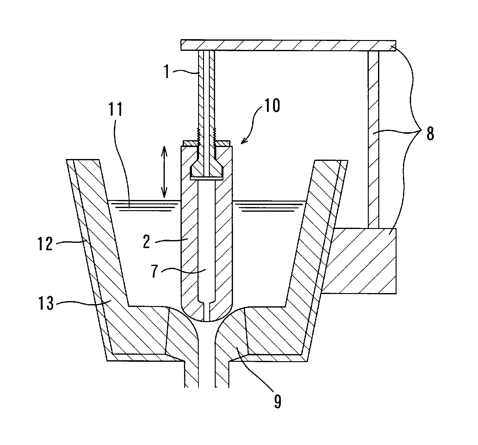
[0082]A stopper structure 10 illustrated in FIG. 1 comprises a refractory stopper 2, and a metal shaft rod 1 which has a distal end mounted in a mounting hole 2a of the refractory stopper 2 through a space 6 serving as a means for absorbing a thermal expansion of the distal end of the shaft rod 1.

[0083]The distal end of the shaft rod 1 is formed in a stepped configuration which comprises a small-diameter portion 1a formed on the side of a base edge of the shaft rod 1, and a large-diameter portion 1b formed on the side of a distal edge of the shaft rod 1 to have a diameter greater than that of the small-diameter portion 1a. The distal end of the shaft rod 1 has an outer peripheral surface including a first tapered sub-surface 4a between the small-diameter portion 1a and large-diameter portion 1b. The mounting hole 2a of the refractory stopper 2 is formed in a configur...

second embodiment

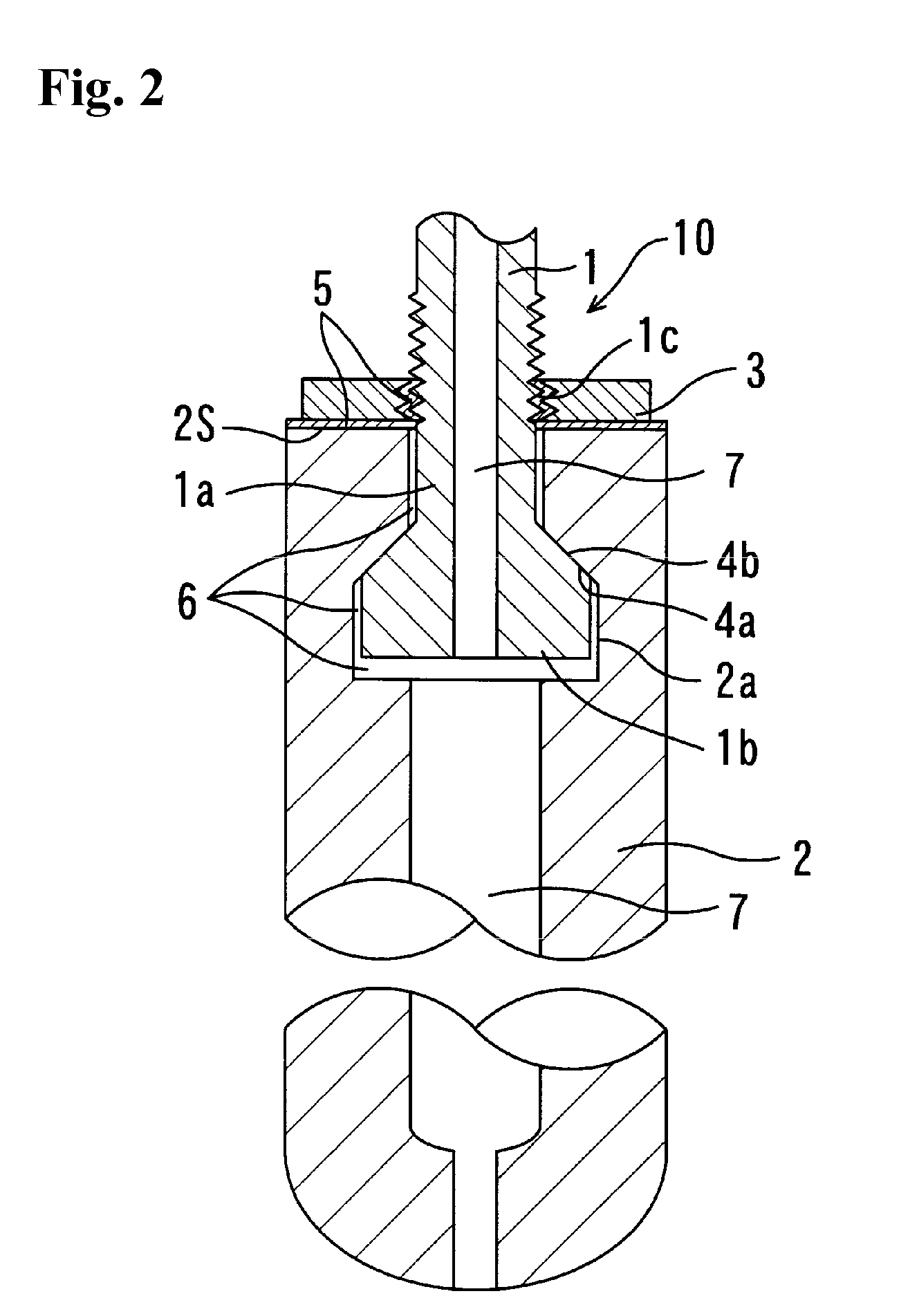
[0088]FIG. 2 is a sectional view showing a stopper structure according to a second embodiment of the present invention. A stopper structure 10 according to the second embodiment is internally provided with a gas passage 7. A contact / joining mechanism between a shaft rod 1 and a refractory stopper 2 in the second embodiment is the same as that in the first embodiment.

[0089]In the second embodiment, the shaft rod 1 is internally provided with a gas passage 7 for supplying gas into a mounting hole 2a of the refractory stopper 2, and the refractory stopper 2 is internally provided with a gas passage 7 penetratingly extending from the mounting hole 2a to a distal end thereof, so as to inject gas from the distal end of the refractory stopper into molten metal, or gas is supplied to the gas passage 7 of the shaft rod 1 to air-cool the shaft rod 1.

[0090]Considering that each of the shaft rod 1 and the refractory stopper 2 is internally provided with the gas passage 7 in the above manner, in...

third embodiment

[0095]FIG. 3 is a sectional view showing a stopper structure according to a third embodiment of the present invention. The stopper structure according to the third embodiment is designed to divide a shaft rod 1 into a first shaft rod segment 1-1 and a second shaft rod segment 1-2.

[0096]The first shaft rod segment 1-1 has a distal end mounted in a mounting hole 2a of a refractory stopper 2, and a threaded portion 1-1a formed in an outer peripheral surface thereof at a position above an upper edge surface 2S of the refractory stopper 2. The second shaft rod segment 1-2 is threadingly engaged with the threaded portion 1-1a of the first shaft rod segment 1-1, and screwed toward the upper edge surface 2S of the refractory stopper. Thus, a lower edge surface of the second shaft rod segment 1-2 is brought into contact with the upper edge surface 2S of the refractory stopper first shaft rod segment, and the first shaft rod segment 1-1 is moved upwardly, so that a first tapered sub-surface 4...


PUM

PropertyMeasurementUnit
Electrical conductanceaaaaaaaaaa
Pressureaaaaaaaaaa
Diameteraaaaaaaaaa

Abstract

The present invention provides a stopper structure capable of preventing loosening of a shaft rod during use, and gas leakage which is likely to occur when the stopper structure is designed to allow gas to pass therethrough. The shaft rod 1 is adapted to be mounted in a mounting hole 2a of a refractory stopper 2, and formed to have an outer peripheral surface including a first tapered sub-surface 4a which increases in diameter toward an axially lower edge of the shaft rod. The mounting hole 2a of the refractory stopper 2 is formed to have an inner surface including a second tapered sub-surface 4b adapted to come into surface contact with the first tapered sub-surface 4a. The shaft rod 1 is adapted to be fastened to the refractory stopper so as to allow the first tapered sub-surface 4a to be brought into close surface contact with the second tapered sub-surface 4b. The distal end of the shaft rod 1 is formed in a configuration satisfying the following relation: tan θ≦D / 2A, wherein: A is a length of the shaft rod 1 between a position of the shaft rod 1 corresponding to an upper edge surface 2S of the refractory stopper, and a start position of the first tapered sub-surface 4a; D is an outer diameter of the first tapered sub-surface 4a at the start position; and θ is a taper angle of the first tapered sub-surface 4a.

Description

TECHNICAL FIELD[0001]The present invention relates to a stopper structure designed to be used, during an operation of discharging molten metal from a vessel via a nozzle, for controlling start and stop of the discharge and a flow rate of the molten metal (hereinafter referred to collectively as “discharge control”), and more particularly to a stopper structure which comprises a refractory stopper serving as a main body thereof, and a shaft rod mounted in the refractory stopper to allow the refractory stopper to be connected to a drive unit.BACKGROUND ART[0002]As a method for performing a discharge control during an operation of discharging molten metal from a vessel via a nozzle, there has been known a technique of arranging a stopper structure inside the vessel, and operating the stopper structure to selectively open and close an interspace defined between a fitting portion thereof and an upper end of the nozzle.[0003]Generally, the stopper structure comprises a refractory stopper ...

Claims


Application Information

Patent Timeline
IPC IPC(8): B22D41/16C04B35/64
CPCB22D41/18B22D41/186
Inventor FUNATO, JUNICHIAZUMA, TAKAHIRO
Owner KROSAKI HARIMA CORP
Why Eureka
Try Eureka