Device and method for measuring the frequency of a signal coded modulated carrier signal

a carrier signal and frequency measurement technology, applied in the direction of frequency to pulse train conversion, digital variable/waveform display, instruments, etc., can solve the problems of device failure and frequency measurement method failur

Active Publication Date: 2010-07-01
NXP BV
View PDF0 Cites 0 Cited by
  • Summary
  • Abstract
  • Description
  • Claims
  • Application Information

AI Technical Summary

Benefits of technology

[0006]It is an object of the invention to provide a device of the type defined in the opening paragraph and a method of the type defined in the second paragraph, in which the disadvantages defined above are avoided as far as possible.

Problems solved by technology

Frequency measuring is usually carried out on uncoded and / or unmodulated signals, because the known measuring methods deliver wrong measuring results when applied to coded signals.
However, the known device fails in applications where the frequency of a signal has to be determined that is present in a signal coded and modulated form, so that it may have DC signal portions and portions where the carrier signal is oscillating with the carrier signal frequency.
However, due to the signal coding conventional frequency measuring methods fail, since they cannot cope with signals showing high frequency portions and DC portions of varying lengths (but still being within the specification of the RFID system).
Another problem is to discriminate between permissible signal coded modulated signals and incidental signals of lower frequencies.
In that case the problem is to discriminate between the DC portion of the modulated signal and the regular duty cycle of the low frequency incidental signal.

Method used


Image

  • Device and method for measuring the frequency of a signal coded modulated carrier signal
  • Device and method for measuring the frequency of a signal coded modulated carrier signal
  • Device and method for measuring the frequency of a signal coded modulated carrier signal

Examples


Embodiment Construction

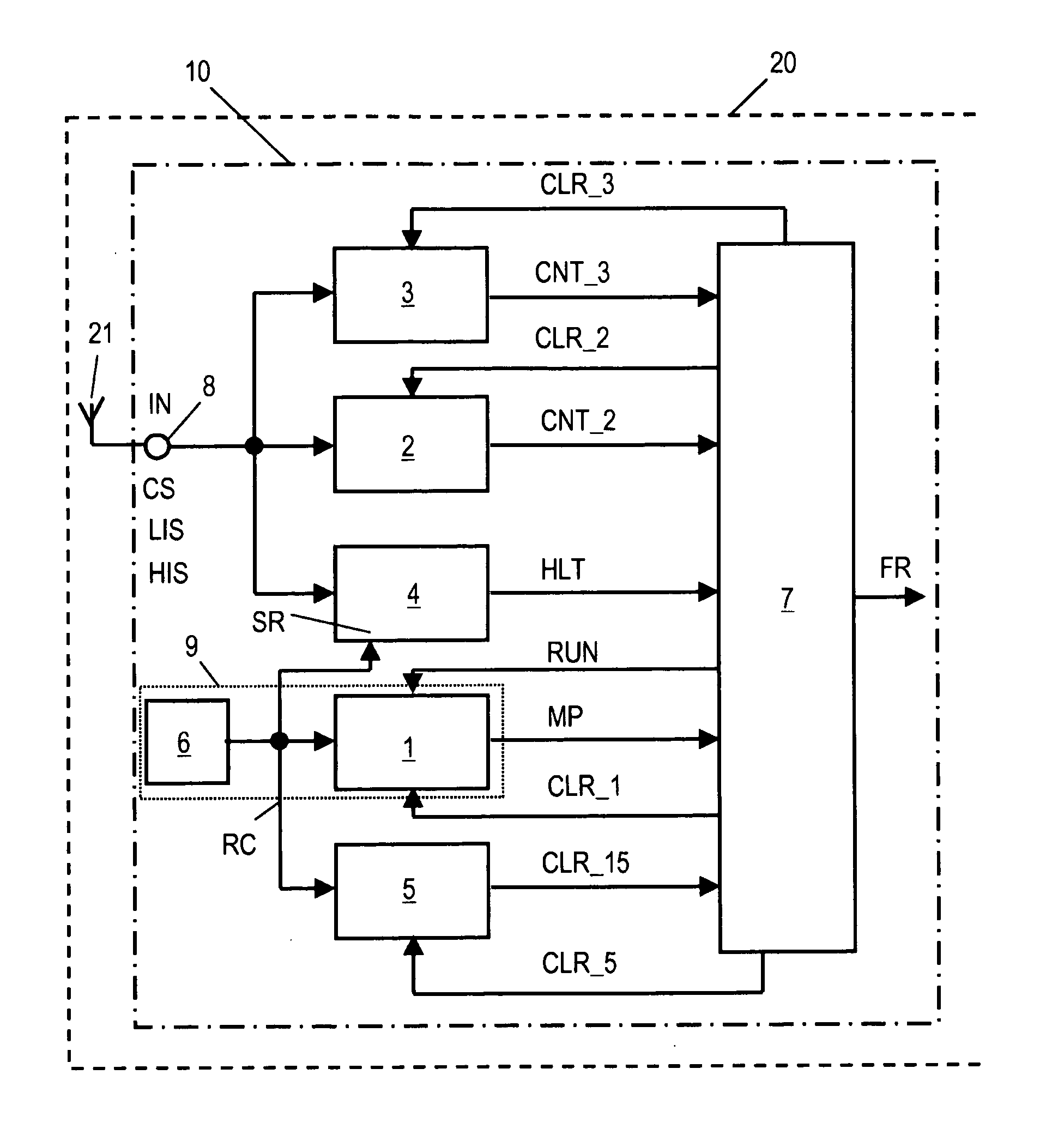
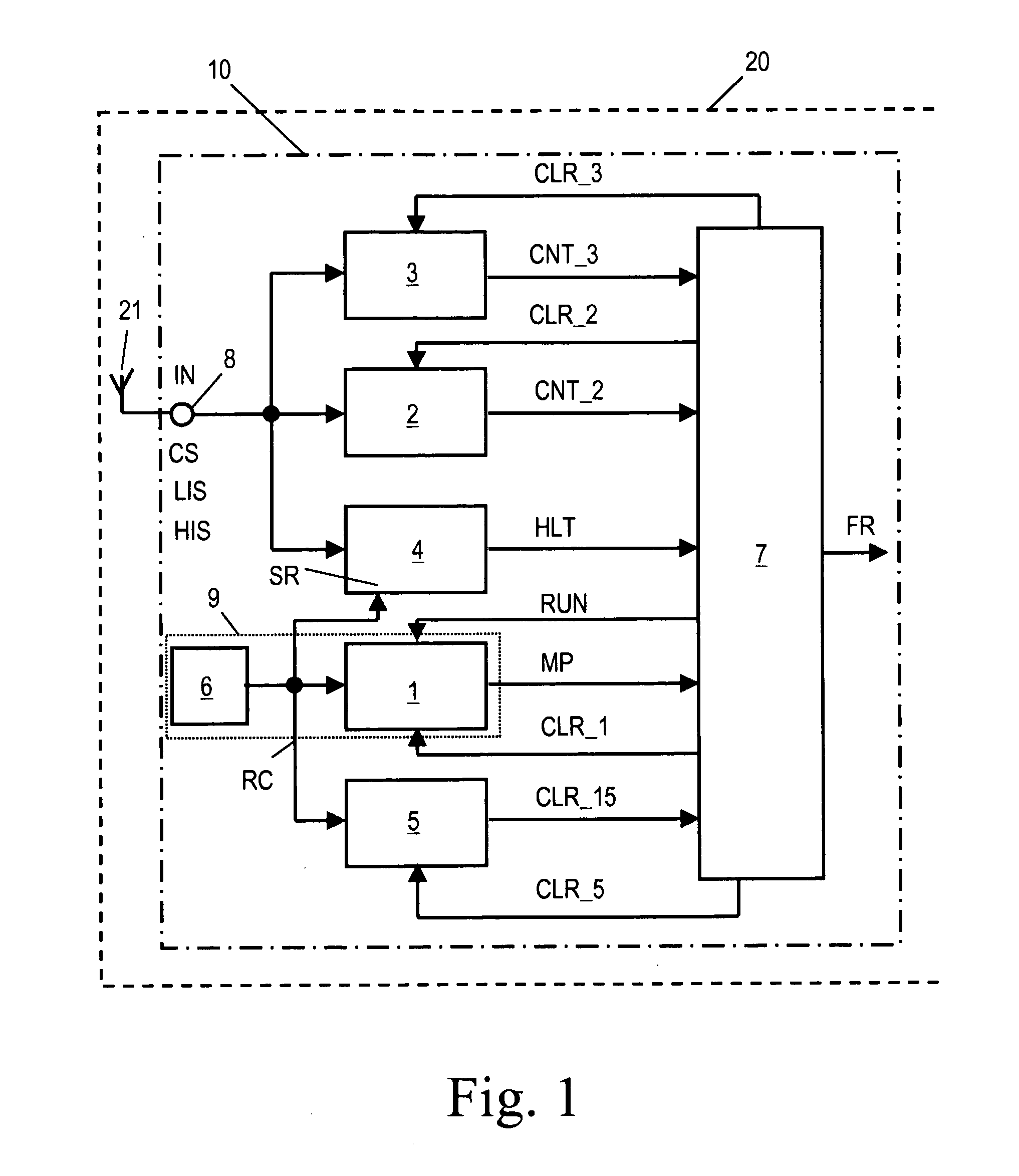
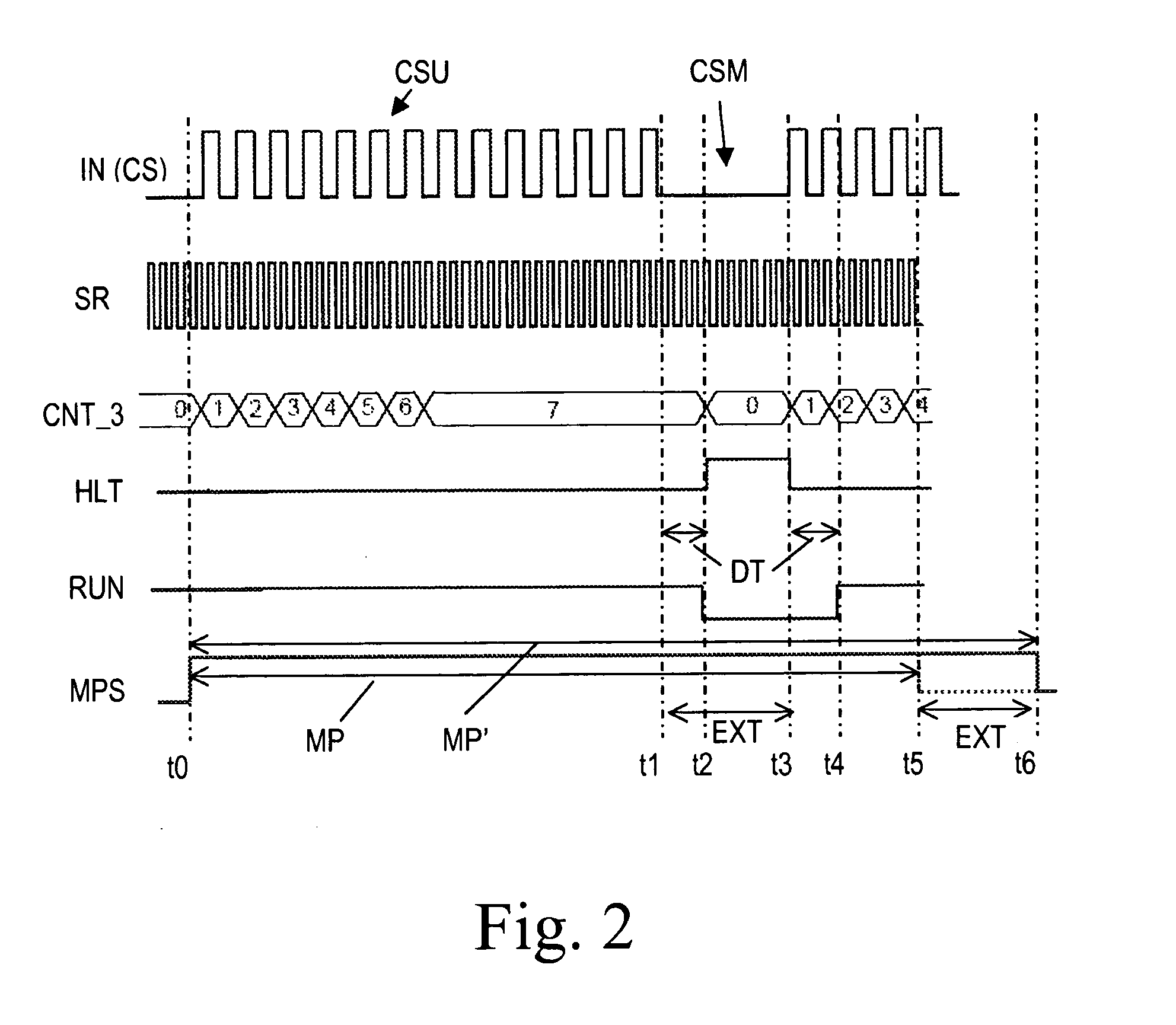
[0034]FIG. 1 shows a schematic block circuit diagram of a frequency measuring device 10 for measuring the frequency of an input signal IN. The frequency measuring device 10 is integrated in an RFID transponder 20 which, except for the frequency measuring device 10, can be configured as a conventional RFID transponder and therefore needs no specific explanations. Persons skilled in the art are well acquainted with the function and design of conventional RFID transponders. The input signal IN is received at an antenna 21 of the RFID transponder 20 and is forwarded to an input port 8 of the frequency measuring device 10. It is expected that the input signal IN comprises a carrier signal CS (see timing diagram of FIG. 2) that contains unmodulated carrier signal portions CSU and modulated carrier signal portions CSM according to a predefined signal coding. Such signals are used in RFID systems and arc wirelessly transmitted from an RFID reader to RFID transponders which are situated in t...


PUM


Abstract

A device (10) for measuring a frequency of an input signal (IN) that is expected to comprise a carrier signal (CS) either being unmodulated (CSU) or being modulated (CSM) according to a predefined signal coding comprises: means (9) for generating a measurement period (MP), an input signal counter (2) which is adapted to count edges of the input signal (IN) during the measurement period (MP), sampling means (4) which are adapted to detect whether the input signal (IN) contains edges, control means (7) which are adapted to read a count value (CNT2) of the input signal counter (2) on expiration of the measurement period (MP) and to derive the frequency (FR) of the input signal from the count value (CNT2) of the input signal counter (2), wherein the means (9) for generating a measurement period (MP) are adapted to extend the measurement period (MP) by a time period (EXT) during which the absence of edges in the input signal (IN) is detected.

Description

FIELD OF THE INVENTION[0001]The invention relates to a device for measuring the frequency of an input signal that is expected to comprise a carrier signal either being unmodulated or being modulated according to a predefined signal coding.[0002]The invention further relates to a method of measuring the frequency of an input signal that is expected to comprise a carrier signal either being unmodulated or being modulated according to a predefined signal coding.[0003]The invention further relates to an RFID transponder.BACKGROUND OF THE INVENTION[0004]Frequency measuring is usually carried out on uncoded and / or unmodulated signals, because the known measuring methods deliver wrong measuring results when applied to coded signals. For instance, document JP 09203756 discloses a network analyzer having a measuring frequency signal source which generates the desired measuring frequency by using a reference frequency given by a built-in reference frequency signal source. Signals from the fre...

Claims


Application Information

Patent Timeline
Patent Type & Authority Applications(United States)
IPC IPC(8): G01R23/02
CPCG01R23/10
Inventor PIEBER, MICHAELBREITFUSS, KLEMENS
Owner NXP BV
Why Eureka
Try Eureka