Passive intermodulation (PIM) distance to fault analyzer with selectable harmonic level

a fault analyzer and harmonic level technology, applied in the direction of transmission monitoring, instruments, line-transmission details, etc., can solve the problems of unwanted signals, interference with system operation, especially troubling, etc., and achieve the effect of removing interference from pcs signals

Active Publication Date: 2010-07-01
ANRITSU CO
View PDF1 Cites 77 Cited by
  • Summary
  • Abstract
  • Description
  • Claims
  • Application Information

AI Technical Summary

Benefits of technology

[0014]Embodiments of the present invention provide a distance to PIM measurement circuit made using a device such as an AWS transceiver that has separate transmit and receive bands, with the AWS transceiver placed in close proximity to another device such as a PCS transceiver, where a band reject filter is used in the AWS device to eliminate interference from the PCS signals. The distance to PIM measurement circuit specifically allows selection of a high harmonic signal to accomplish test measurements so that signals are not blocked by the band reject filter.
[0015]In embodiments of the invention, the distance to PIM measurement circuit includes two frequency sources F1 and F2 that are provided through a combiner for a CW characterization of the PIM circuit. To enable distance determination, an FM measurement is created by using a saw tooth offset sweep generator attached to one of the two frequency sources operating at a significantly lower frequency than the frequency source. With downconversion and processing of a selected harmonic signal from the PIM circuit, the FM signal provides a frequency variation that is converted using a Fourier transform to time domain, enabling determination of the distance and magnitude of the PIM source.

Problems solved by technology

PIM has surfaced as a problem for cellular telephone technologies such as Global System for Mobile Communications (GSM), Advanced Wireless Service (AWS) and Personal Communication Service (PCS) systems.
Cable assemblies connecting a base station to an antenna on a tower using these cellular systems typically have multiple connectors that cause PIMs that can interfere with system operation.
When these multiple signals are allowed to share the same signal path in a nonlinear transmission medium, the unwanted signals can occur.
This can be especially troubling when multiple connectors are involved as can be present in a PCS / AWS site tower.
A problem with current test systems is that when an AWS system and a PCS system are in close proximity, a filter is provided in the AWS system to remove PCS components.
The band reject filter will eliminate the 1732.5 MHz PIM test signal that is being measured by the system of FIG. 1, as described above, so testing for 3rd order signals cannot be accomplished.

Method used


Image

  • Passive intermodulation (PIM) distance to fault analyzer with selectable harmonic level
  • Passive intermodulation (PIM) distance to fault analyzer with selectable harmonic level
  • Passive intermodulation (PIM) distance to fault analyzer with selectable harmonic level

Examples


Embodiment Construction

I. Third Order Harmonic Distance to Fault Analyzer

[0037]Initially systems are described that can detect distance to PIM using a 3rd order harmonics. Systems that allow detection of harmonics higher than a 3rd order are described in a subsequent section II.

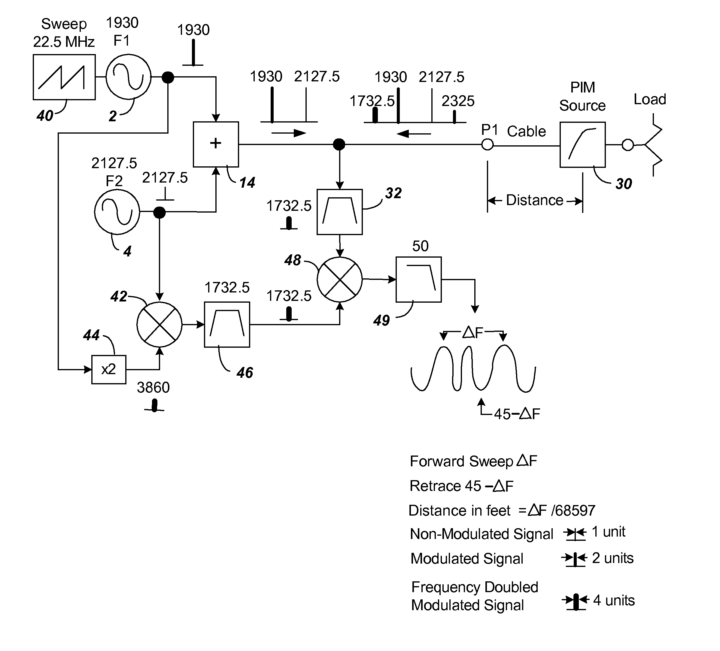
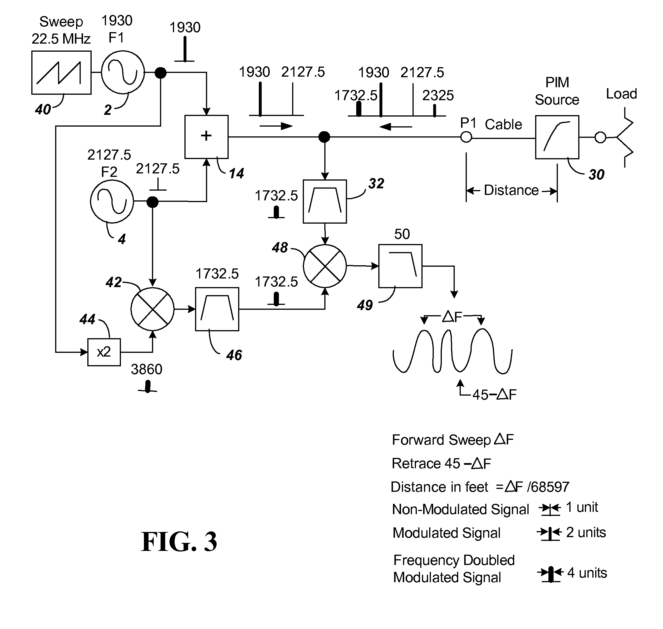
[0038]FIG. 3 shows the block diagram of components of a first distance to fault analyzer using FM-CW and a 3rd order signal as a means of determining distance in a PIM measurement device. The FM sweep is introduced using sweep generator 40. The sweep generator 40 is connected to F1 source 2. For purpose of illustration, the sweep generator 40 is shown creating a 1.4844 uS period saw tooth causing a + / −11.25 MHz modulation (ranging 22.5 MHz as shown) that is added to F1 of source 2. The FM sweep signal F1 and the fixed signal F2 when modified by the PIM source will produce the additional signals 2*(F1+FM)−F2 and 2*F2−(F1+FM). The delayed in time (distance) signal 2*(F1+FM)−F2 will be mixed with an internally generated non-delayed in...


PUM


Abstract

A distance to PIM measurement circuit is made using a device such as an AWS transceiver that has separate transmit and receive bands. With a typical AWS transceiver placed in close proximity to a PCS transceiver, the AWS device will include a band reject filter to eliminate interference from the PCS signals. The PIM measurement circuit includes two frequency sources F1 and F2 that are provided through a combiner for characterization of the PIM circuit. To enable distance determination, an FM measurement is created by using a offset sweep generator attached to one of the two frequency sources. To avoid frequencies blocked by the band reject filter, a desired harmonic of a test PIM harmonic signal is selected outside the band of the band reject filter. In one embodiment, a reference signal is provided by mixing a signal from an ×M multiplier connected to the F1 source with an ×N multiplier signal connected to the F2 source, the mixed output being filtered to select the desired harmonic reference signal to avoid the band reject filter. In another embodiment, a reference signal is created by generating all harmonics of the combined F1 and F2 signal using a series connected amplifier and clipping diodes with a filter again used to select the desired harmonic reference signal to avoid the band reject filter.

Description

CLAIM FOR PRIORITY[0001]This application is a continuation-in-part of application Ser. No. 12 / 246,330 filed on Oct. 6, 2008, entitled “Calibrated Two Port Passive Intermodulation (PIM) Distance to Fault Analyzer,” the entire contents of which are incorporated herein by reference.BACKGROUND[0002]1. Technical Field[0003]The present invention relates to a single (reflected) or a two port (transmission) distance to fault analyzer configured to measure passive intermodulation (PIM) created by two separate signal sources as well as to measure distance to a fault creating PIM.[0004]2. Related Art[0005]PIM is an unwanted signal or signals generated by the non-linear mixing of two or more frequencies in a passive device such as a connector or cable. PIM has surfaced as a problem for cellular telephone technologies such as Global System for Mobile Communications (GSM), Advanced Wireless Service (AWS) and Personal Communication Service (PCS) systems. Cable assemblies connecting a base station ...

Claims


Application Information

Patent Timeline
Patent Type & Authority Applications(United States)
IPC IPC(8): G01R31/08
CPCG01R31/11H04B3/46H04B17/0085H04B17/17
Inventor BRADLEY, DONALD ANTHONY
Owner ANRITSU CO
Why Eureka
Try Eureka