

Tunable Impedance Matching Circuit
a matching circuit and impedance technology, applied in the field of tunable impedance matching circuits, can solve the problems of increasing the loss of the matching circuit, device cannot be integrated, and the device to operate under non-optimal conditions at different bands of operation, so as to achieve simple configuration and easy integration in the ics
- Summary
- Abstract
- Description
- Claims
- Application Information
AI Technical Summary
Benefits of technology
Problems solved by technology
Method used
Image

Examples
Embodiment Construction
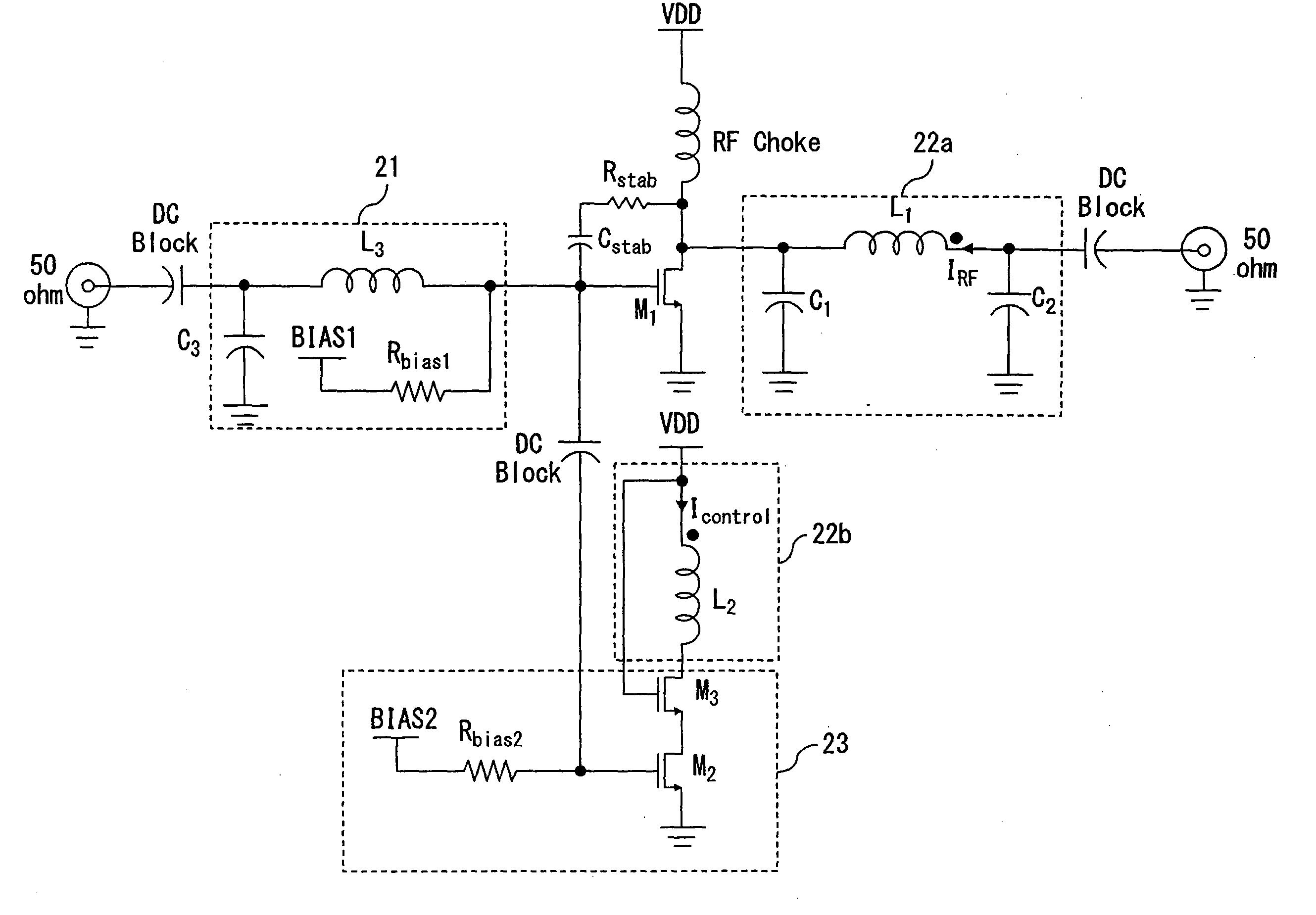
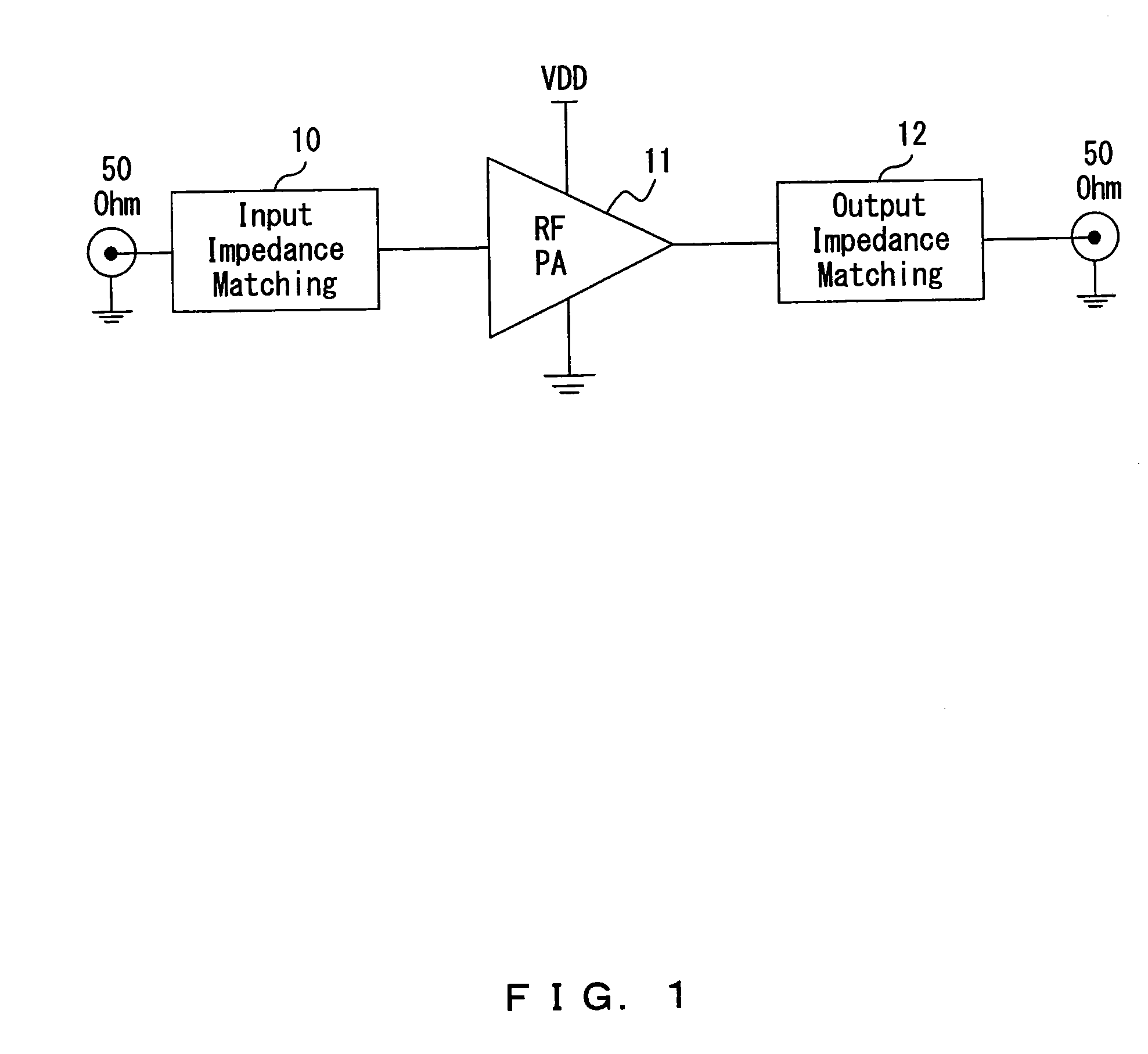
[0027]The embodiments of the present invention relate to the tunable impedance matching circuit that is applicable, for example, to the field of RF power amplifiers to be used in wireless transmitters and transceivers and, more specifically, to techniques that allow these amplifiers to operate in different frequency bands with optimal performance.
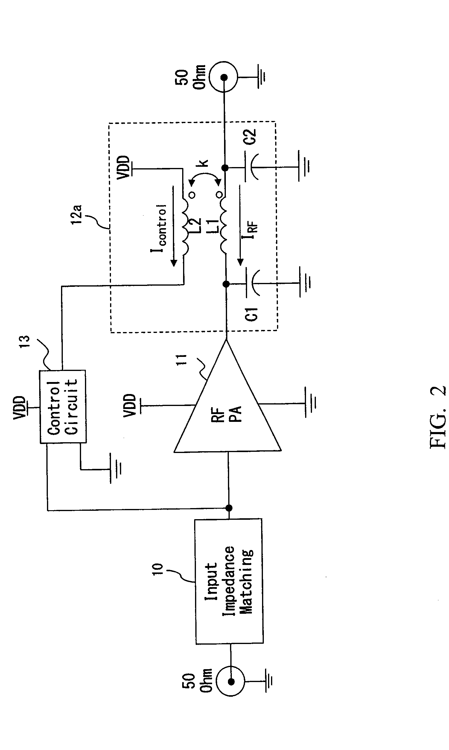
[0028]An RF power amplifier is improved by, for example, making it tunable in frequency within specific operating frequency bands by using the tunable impedance matching circuit of the embodiment. The impedance matching circuit of the embodiment employs coupled-inductors. Via the application of a control current into one of the windings of these coupled-inductors, the impedance matching circuit becomes tunable in frequency, thereby allowing the load impedance of, for example, the power amplifier to be set to an optimum value at each operating band.
[0029]In the application of the embodiment of the present invention, a frequency tunable RF po...
PUM
 Abstract
Description
Claims
Application Information