

Monostable permanent magnetic actuator using laminated steel core
a permanent magnetic actuator and laminated steel technology, applied in the direction of cores/yokes, magnets, magnetic bodies, etc., can solve the problems of actuators with complicated structures, actuators with long operation time, and lowering the operation of the mover, so as to reduce the eddy current
- Summary
- Abstract
- Description
- Claims
- Application Information
AI Technical Summary
Benefits of technology
Problems solved by technology
Method used
Image

Examples
Embodiment Construction
[0040]Description will now be given in detail of the present invention, with reference to the accompanying drawings.
[0041]Hereinafter, an actuator according to the present invention will be explained in more detail with reference to the attached drawings.
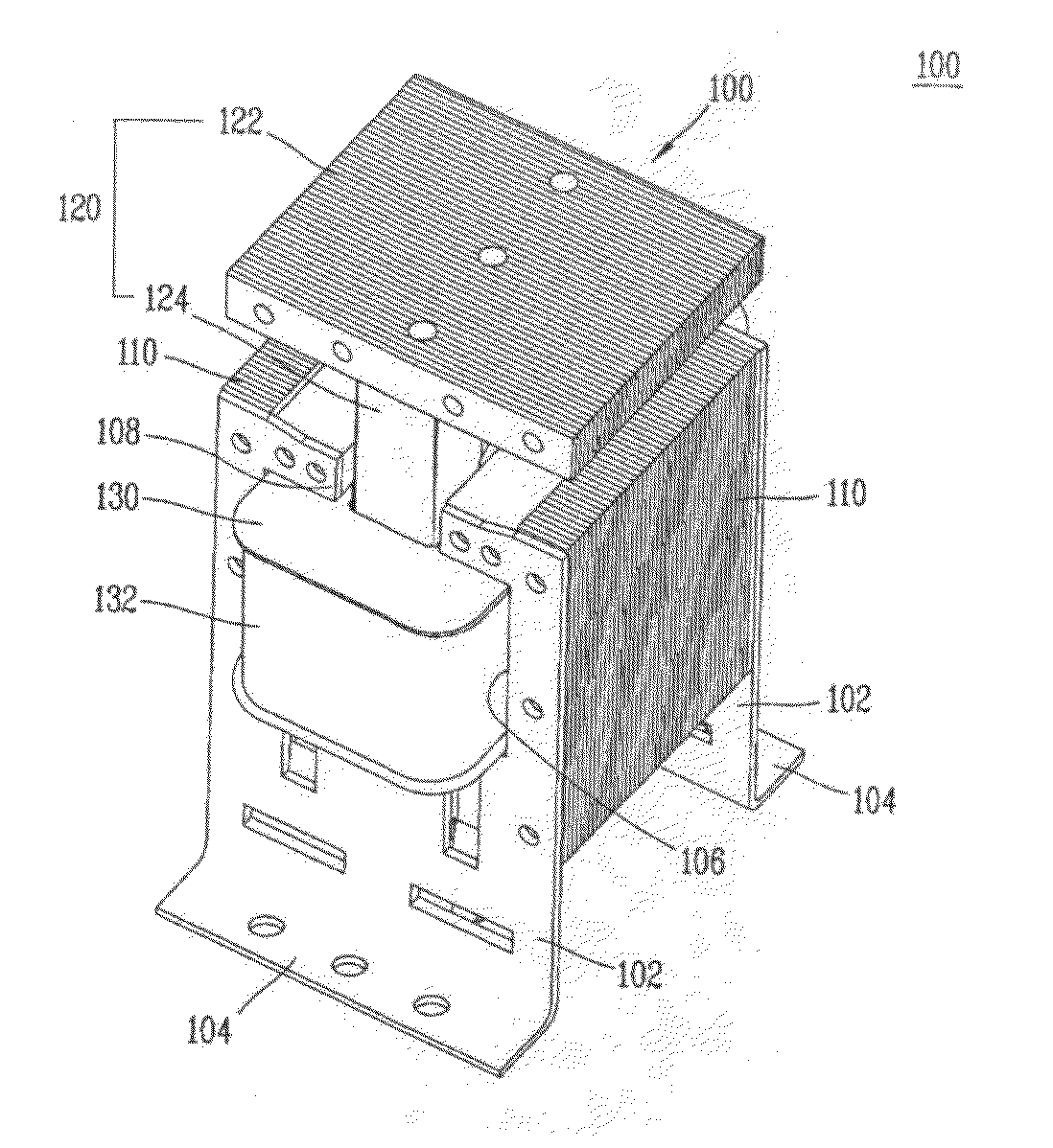
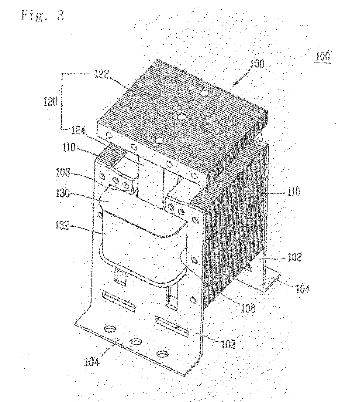
[0042]Referring to FIG. 3, an actuator 100 according to one embodiment of the present invention comprises one pair of fixed plates 102 disposed to face each other. The fixed plates 102 are configured to provide coupling surfaces with external devices as lower ends 102 thereof are bent. An opening 106 through which a bobbin and a coil that will be later explained are partially exposed out is formed at an upper side of the fixed plates 102. And, a cut-out portion 108 is formed at a central portion of an upper end of the fixed plates 102, through which a head of a mover 120 can be moved in upper and lower directions. Lamination cores 110 are fixed between said one pair of fixed plates 102. As the fixed plates 102 and the lamination cor...
PUM
 Abstract
Description
Claims
Application Information