Zoom lens system, imaging device and camera

Inactive Publication Date: 2010-07-01
PANASONIC CORP
View PDF12 Cites 38 Cited by
  • Summary
  • Abstract
  • Description
  • Claims
  • Application Information

AI Technical Summary

Benefits of technology

[0015]An object of the present invention is to provide: a high-performance zoom lens system that has a reduced size with a short overall length of lens system and still has a high resolution and a relat

Problems solved by technology

Nevertheless, in the zoom lenses and the optical systems disclosed in the patent documents, although size reduction is achieved to an extent applicable to thin and compact digital cameras, their zooming ratio is as low as approximately 3 or smaller and does not satisfy the requirement for digital cameras in recent years.
Further, the zoom lenses and the optical systems disclosed in the patent documents do not satisfy the requirements for digital ca

Method used


Image

  • Zoom lens system, imaging device and camera
  • Zoom lens system, imaging device and camera
  • Zoom lens system, imaging device and camera

Examples


embodiments i-1 to i-4

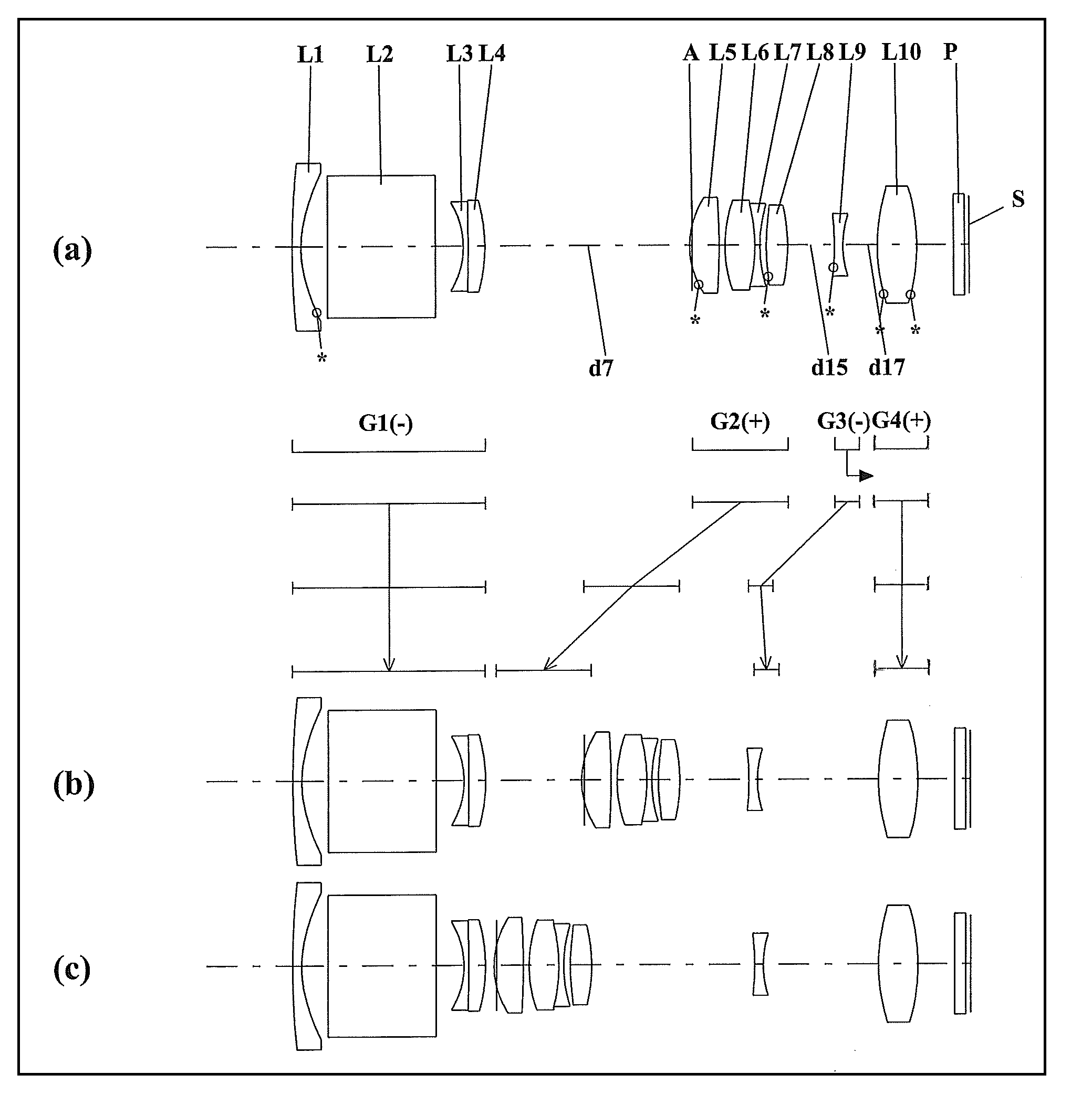
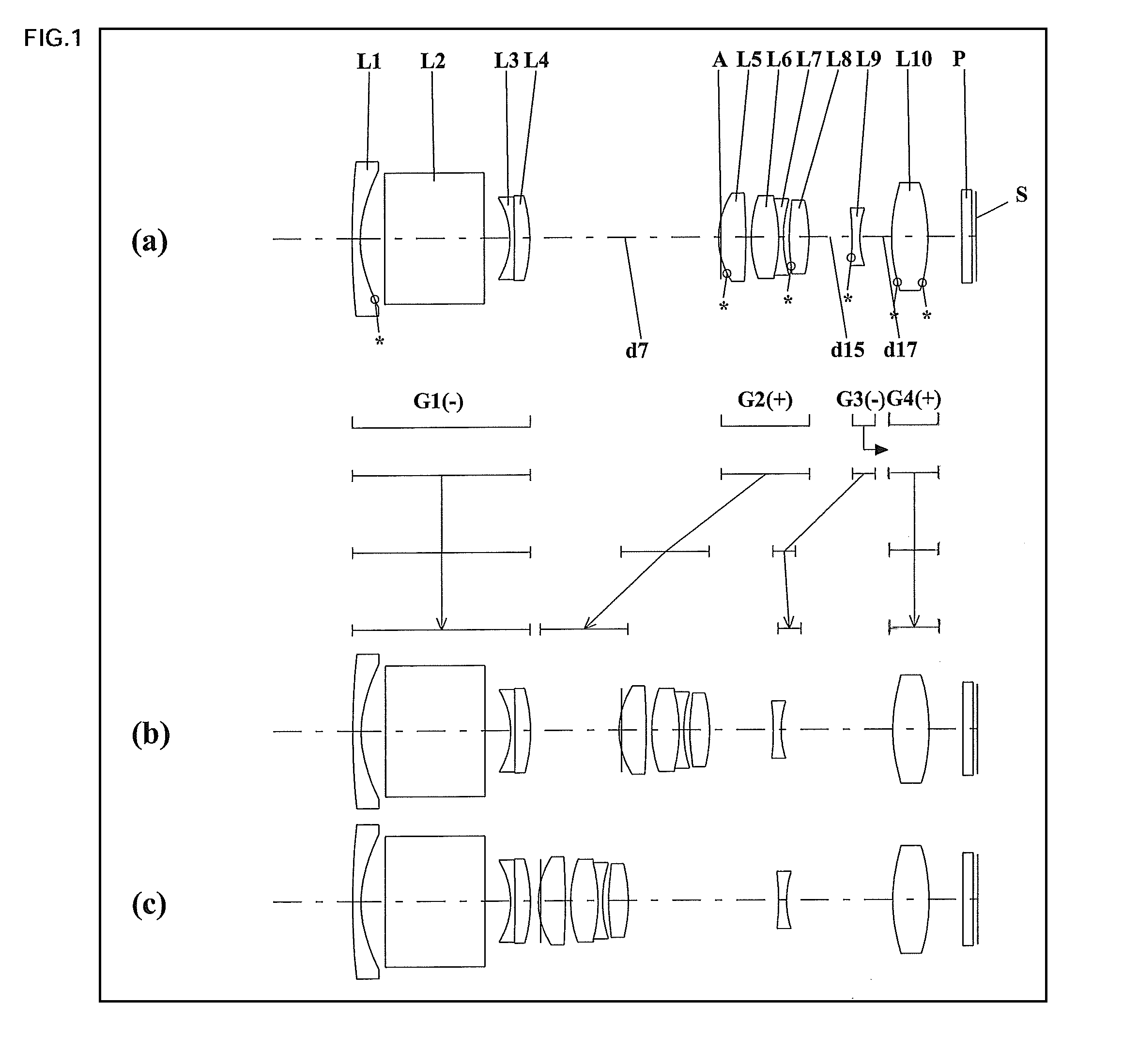
[0254]FIGS. 1, 4, 7 and 10 are lens arrangement diagrams of zoom lens systems according to Embodiments I-1 to I-4, respectively.

[0255]Each of FIGS. 1, 4, 7 and 10 shows a zoom lens system in an infinity in-focus condition. In each Fig., part (a) shows a lens configuration at a wide-angle limit (in the minimum focal length condition: focal length fW), part (b) shows a lens configuration at a middle position (in an intermediate focal length condition: focal length fM=√{square root over ( )}(fW*fT)), and part (c) shows a lens configuration at a telephoto limit (in the maximum focal length condition: focal length fT). Further, in each Fig., each bent arrow located between part (a) and part (b) indicates a line obtained by connecting the positions of each lens unit respectively at a wide-angle limit, a middle position and a telephoto limit. Thus, in the part between the wide-angle limit and the middle position and the part between the middle position and the telephoto limit, the position...

embodiment i-5

[0317]FIG. 13 is a schematic construction diagram of a digital still camera according to Embodiment I-5. In FIG. 13, the digital still camera comprises: an imaging device having a zoom lens system 1 and an image sensor 2 composed of a CCD; a liquid crystal display monitor 3; and a body 4. The employed zoom lens system 1 is a zoom lens system according to Embodiment I-1. In FIG. 13, the zoom lens system 1 comprises a first lens unit G1, an aperture diaphragm A, a second lens unit G2, a third lens unit G3 and a fourth lens unit G4. In the body 4, the zoom lens system 1 is arranged on the front side, while the image sensor 2 is arranged on the rear side of the zoom lens system 1. On the rear side of the body 4, the liquid crystal display monitor 3 is arranged, while an optical image of a photographic object generated by the zoom lens system 1 is formed on an image surface S.

[0318]As such, when the zoom lens system according to Embodiment I-1 is employed in a digital still camera, a sma...

embodiments ii-1 to ii-4

)

[0321]FIGS. 14, 17, 20 and 23 are lens arrangement diagrams of zoom lens systems according to Embodiments II-1 to II-4, respectively.

[0322]Each of FIGS. 14, 17, 20 and 23 shows a zoom lens system in an infinity in-focus condition. In each Fig., part (a) shows a lens configuration at a wide-angle limit (in the minimum focal length condition: focal length fW), part (b) shows a lens configuration at a middle position (in an intermediate focal length condition: focal length fM=√{square root over ( )}(fW*fT)), and part (c) shows a lens configuration at a telephoto limit (in the maximum focal length condition: focal length fT). Further, in each Fig., each bent arrow located between part (a) and part (b) indicates a line obtained by connecting the positions of each lens unit respectively at a wide-angle limit, a middle position and a telephoto limit. Thus, in the part between the wide-angle limit and the middle position and the part between the middle position and the telephoto limit, the...


PUM


Abstract

A zoom lens system, in order from an object side to an image side, comprising a first lens unit having negative optical power, a second lens unit having positive optical power, and at least one subsequent lens unit having optical power, wherein in zooming from a wide-angle limit to a telephoto limit, the lens units are moved along an optical axis such that an air space between at least any two lens units among the lens units should vary, so that variable magnification is achieved, wherein the first lens unit includes a lens element having a reflecting surface for bending a light beam incident from the object, and wherein the condition is satisfied: 0.20<|fG1|/fT<0.52 (fT/fW≧4.0, fG1 is a composite focal length of the first lens unit, and each of fT and fW is a focal length of the entire system at a telephoto limit or a wide-angle limit), an imaging device and a camera are provided.

Description

CROSS-REFERENCE TO RELATED APPLICATION[0001]This application is based on application Nos. 2008-330997, 2008-330998, 2008-330999, 2008-331000 and 2008-331002 filed in Japan on Dec. 25, 2008, the contents of which are hereby incorporated by reference.BACKGROUND OF THE INVENTION[0002]1. Field of the Invention[0003]The present invention relates to a zoom lens system, an imaging device and a camera. In particular, the present invention relates to: a high-performance zoom lens system that has a reduced size with a short overall length of lens system and still has a high resolution and a relatively high zooming ratio of 4 or greater and that is satisfactorily applicable in wide-angle image taking; an imaging device employing this zoom lens system; and a thin and compact camera employing this imaging device.[0004]Further, in particular, the present invention relates to: a high-performance zoom lens system that has a remarkably reduced size with a short overall length of lens system and stil...

Claims


Application Information

Patent Timeline
IPC IPC(8): G02B15/177G02B27/64
CPCG02B15/177G02B27/646G02B15/144511
Inventor YAMAGUCHI, SHINJINISHIOKA, TAKEHIROIMAOKA, TAKUYAYOSHINAGA, SHUNICHIRO
Owner PANASONIC CORP
Why Eureka
Try Eureka