
High efficiency universal input switching power supply

a power supply and high-efficiency technology, applied in electrical energy, process and machine control, instruments, etc., can solve the problems of poor transforming efficiency of universal switching power, and inability of each universal switching power supply to provide good transforming efficiency for different line voltages, etc., to achieve the effect of increasing the whole transforming efficiency

Inactive Publication Date: 2010-07-01
ACBEL POLYTECH INC
View PDF7 Cites 52 Cited by
  • Summary
  • Abstract
  • Description
  • Claims
  • Application Information

AI Technical Summary

Benefits of technology

[0011]An objective of the present invention is to provide a universal input switching power supply automatically having a parallel and serial type DC to DC converter changes a physical circuit thereof for different AC power source to increase the whole transforming efficiency.
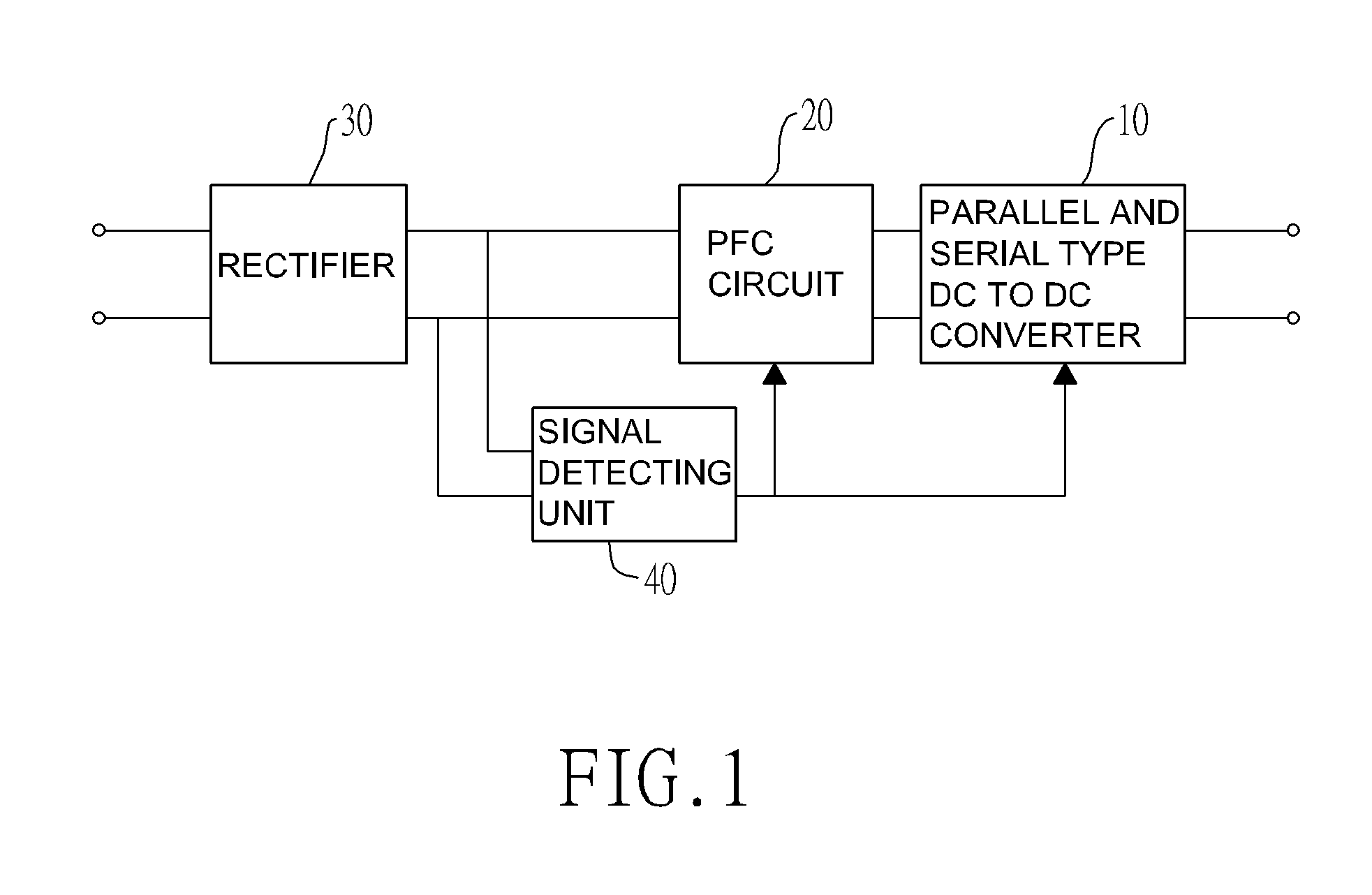
[0012]The universal input switching power supply has the rectifier, a signal detecting unit detecting a voltage of an external AC power and outputting a detecting signal, a PFC circuit converts a first DC power from the rectifier to a second DC power with different voltage according to the detecting signal; and a parallel and serial type DC to DC converter converting the second DC power with different voltage to a constant voltage of the third DC power. The parallel and serial type DC to DC converter has a transformer having a primary and secondary coils and physically changes a turn ratio of the primary and secondary coils of a transformer thereof according to a voltage ratio of the second DC power and the third DC power. Accordingly, the universal input switching power supply has good transforming efficiency at different AC power source conditions.

Problems solved by technology

However, a transforming efficiency of the universal switching power is not good, especially coupling to 110V AC power source (AC IN).
Therefore, the universal switching power efficiency is also not good, especially coupling to the high voltage of the AC power source.
Based on foregoing description, each of the universal switching power supplies can not provide good transforming efficiency for different line voltages of the AC power sources.

Method used


Image

  • High efficiency universal input switching power supply
  • High efficiency universal input switching power supply
  • High efficiency universal input switching power supply

Examples


Embodiment Construction

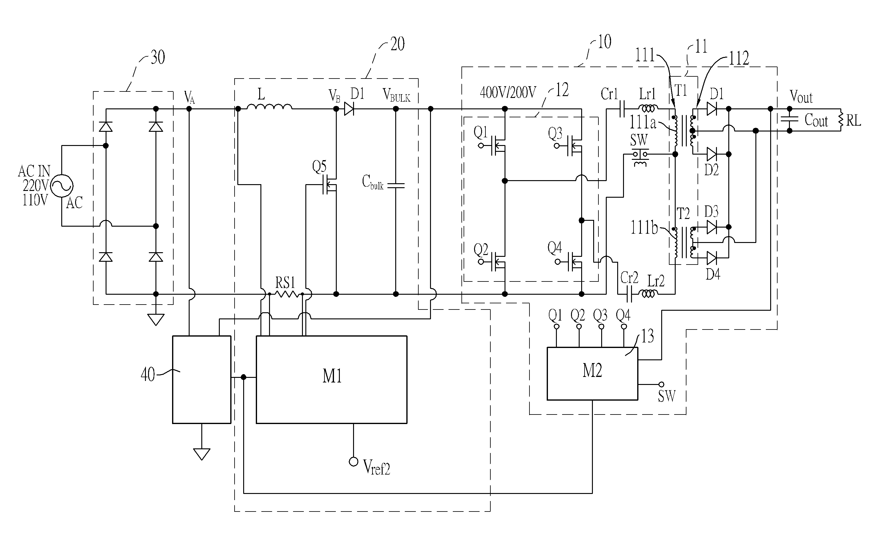
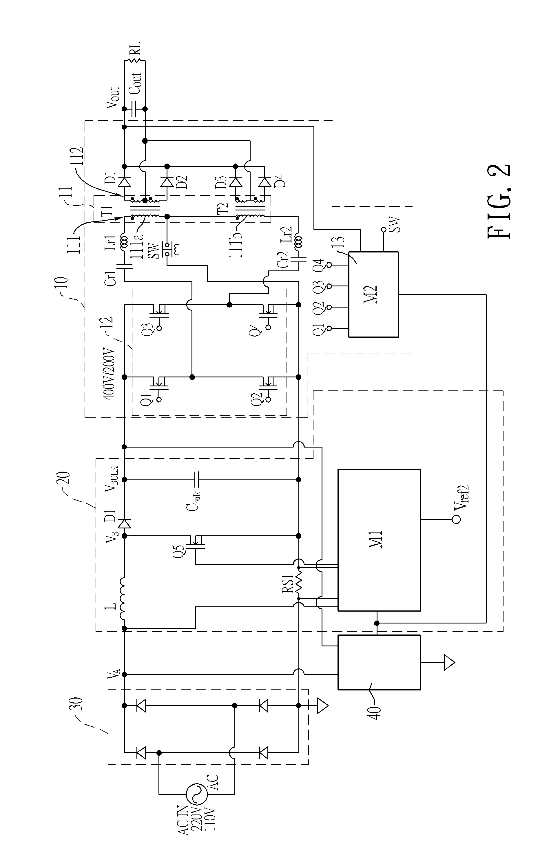
[0029]With reference to FIGS. 1 and 2, a universal input switching power supply has a rectifier (30), a signal detecting unit (40), a power factor connection circuit (hereinafter PFC circuit) (20) and a parallel and serial type DC to DC converter (10).

[0030]Multiple inputs of the rectifier (30) are coupled to an external AC power (AC IN) and converts the external AC power (AC IN) to a first DC power (VA). The first DC power (VA) is output to the outputs of the rectifier (30). The signal detecting unit (40) is connected to the output of the rectifier (30) to detect a status of the first DC power (VA) and output a detecting signal including voltage status, current status . . . etc. statuses. The PFC circuit (20) has inputs and outputs. The inputs of the PFC circuit (20) are connected to the outputs of the rectifier (30) and the signal detecting unit (40) to obtain the first DC power (VA) and receive the detecting signal. The PFC circuit (20) converts the first DC power (VA) to a secon...


PUM


Abstract

A universal input switching power supply has the rectifier, a signal detecting unit detecting a voltage of an external AC power and outputting a detecting signal, a PFC circuit converts a first DC power from the rectifier to a second DC power with different voltage according to the detecting signal; and a parallel and serial type DC to DC converter converting the second DC power with different voltage to a constant voltage of the third DC power. The parallel and serial type DC to DC converter has a transformer having a primary and secondary coils and physically changes a turn ratio of the primary and secondary coils of a transformer thereof according to a voltage ratio of the second DC power and the third DC power. Accordingly, the universal input switching power supply has good transforming efficiency at different AC power source conditions.

Description

BACKGROUND OF THE INVENTION[0001]1. Field of the Invention[0002]The present invention is related to a universal input switching power supply, and more particularly to a universal input switching power supply having a parallel and serial type DC to DC converter to increase transforming efficiency.[0003]2. Description of the Related Art[0004]The universal input switching power supply may use a high line voltage range (185V to 265V) of an AC power source or a low line voltage range (90V to 130V) of an AC power source and provides a constant output voltage of a DC power source. Every country sets a normal high and low line voltages of the AC power, for example, in Taiwan, the normal high line voltage is 220 VAC and the normal low line voltage is 110 VAC.[0005]With reference to FIG. 11, a conventional universal input switching power supply mainly has a full bridge rectifier (50), a power factor corrector (hereinafter PFC) circuit (51) and a DC to DC converting circuit (52). The full brid...

Claims


Application Information

Patent Timeline
IPC IPC(8): H02M3/335
CPCH02M1/10H02M3/28Y02P80/112Y02P80/10
Inventor LIN, WEI-LIANG
Owner ACBEL POLYTECH INC
Learn More