Replay transmission device and replay transmission method
Active Publication Date: 2010-07-01
PANASONIC CORP
View PDF18 Cites 79 Cited by
Summary
Abstract
Description
Claims
Application Information
AI Technical Summary
This helps you quickly interpret patents by identifying the three key elements:
Problems solved by technology
Method used
Benefits of technology
Benefits of technology
[0076]According to the present invention, buffer control is performed from two perspectives, namely, equalization of a packet remaining amount between buffers which are provided in each relay device in correspondence with different forwarding destinations (self-optimization), and equalization of a packet remaining amount between buffers of relay devices on a same transmission path (total optimization). Through such buffer control, contention for transmission bandwidth allocation between buffers in each relay device and contention for transmission bandwidth allocation between relay devices can both be solved. As a result, congestion in an ad hoc network is suppressed, with it being possible to achieve high-quality transmission.
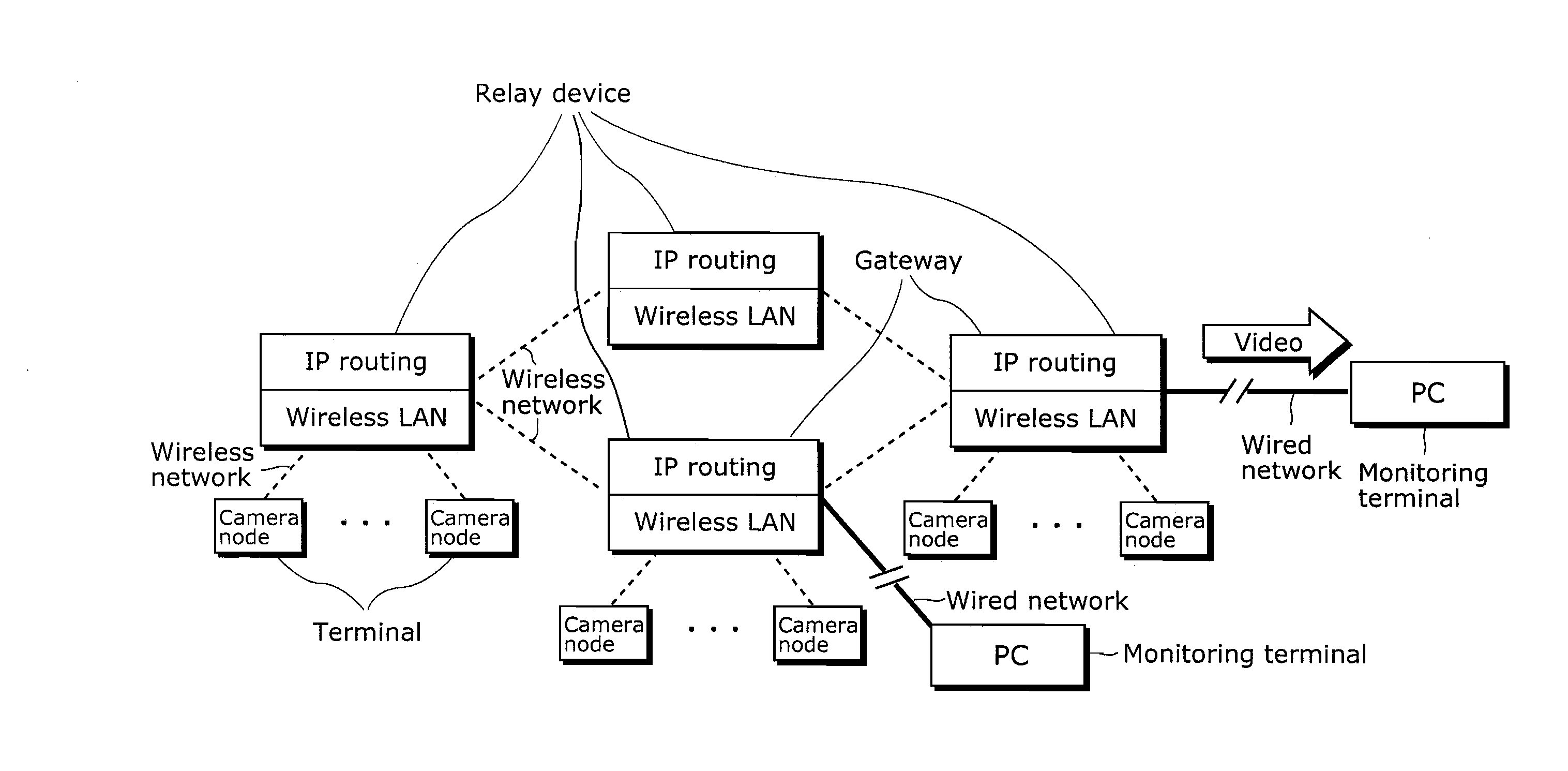
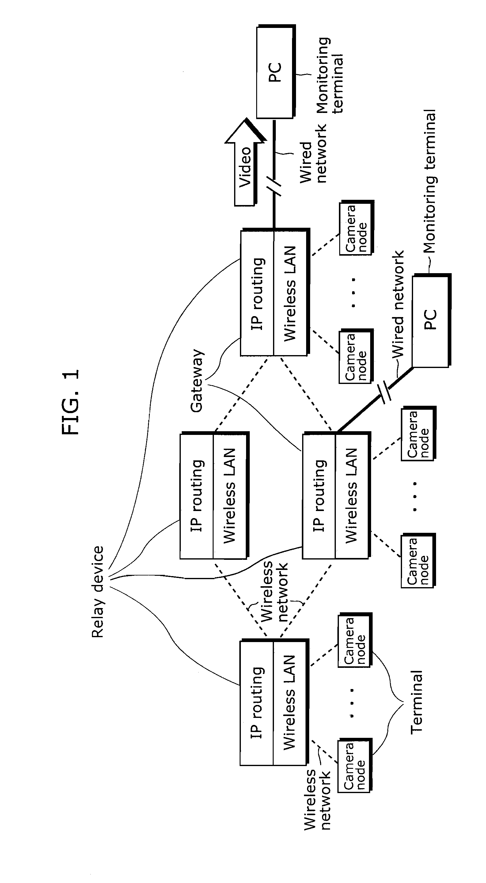
In a network where a plurality of terminals (including a transmission terminal and a reception terminal) and relay devices are connected to each other, “congestion” can occur when data is transmitted from the transmission terminal to the reception terminal via relay devices.
This causes problems such as a transmission error (data loss) and a data reception delay.
For example, congestion is such a state where, as a result of data that exceeds a buffer capacity being transmitted to the relay device, a buffer overflow occurs and a data loss or a time delay in transmitting to the forwarding destination ensues.
Which is to say, congestion means that transmission packets concentrate and crowd in one place and consequently a data loss or a data transmission delay occurs.
In the ad hoc network environment, all terminals and relay devices are connected wirelessly, so that transmission between a transmission terminal and a relay device, between relay devices, and between a relay device and a reception terminal tends to become unstable.
Hence a data loss or a time delay due to congestion arises easily.
One type of imbalance is an inequality in packet remaining amount between buffers that correspond to different forwarding destinations in one relay device.
This causes an imbalance in loss or delay between a plurality of traffic flows.
The other type of imbalance is an inequality in packet remaining amount between buffers of relay devices that are located on a same transmission path.
This induces congestion in a relay device on the transmission path.
Therefore, contention arises when allocating resources among relay devices.
Method used
Image
Click on the blue label to locate the original text in one second.
Reading with bidirectional positioning of images and text.
Examples
examples
[0443]FIG. 21 is an explanatory diagram of specific examples of transmission amount control for self-optimization and total optimization based on Expression 14 (Expressions 7 and 13), and assumed conditions of these examples.
[0444]A first example relates to a method of suppressing an imbalance in data remaining amount between transmission buffers in the present relay device (self-optimization) and suppressing an imbalance in data remaining amount between transmission buffers of the present relay device and its cooperative party (total optimization), by adjusting a transmission amount of each transmission buffer through scheduling based on Expression 14 (Expressions 7 and 13).
[0445]In the self-optimization of the first example, scheduling (transmission amount) is adjusted by using a data remaining amount of each transmission buffer in the present relay device as a present relay device transmission buffer state.
[0446]In the total optimization of the first example, scheduling (transmis...
first example
Transmission Amount Control by Scheduling
[0458]FIG. 22 is an explanatory diagram of a method of adjusting a transmission amount by transmission buffer scheduling.
[0459]As the method of transmission amount adjustment by transmission buffer scheduling, a method such as Weighted Round Robin (WRR) can be used to adjust the amount of data transmitted from each transmission buffer.
[0460]WRR is a method of adjusting transmission amount xn,i of each transmission buffer in accordance with weight wn,i assigned to the transmission buffer.
[0461]In FIG. 22, when an amount of data transmitted from relay device n is denoted by xn,i an amount of data transmitted from each transmission buffer is obtained by dividing transmission amount xn in proportion to weight wn,i assigned to each transmission buffer.
[0462]Accordingly, control of transmission amount xn,i by scheduling can be realized by adjusting weight wn,i of each transmission buffer based on the control expressions of Expressions 7 and 13.
[046...
second example
Transmission Amount Control by Packet Discard
[0494]FIG. 23 is an explanatory diagram of packet discard in a transmission buffer.
[0495]The adjustment of the buffer remaining amount of each transmission buffer in the relay device can be achieved not only by controlling the data transmission amount, but also by using a packet discard method such as Random Early Detection (RED).
[0496]RED is a technique of randomly selecting a packet in a transmission buffer and discarding the selected packet in advance by adjusting discard rate y in accordance with a buffer remaining amount (time average) of the transmission buffer, to thereby avoid congestion.
[0497]FIG. 23 is a graph showing a relation between the buffer remaining amount (time average) of the transmission buffer and the probability of packet discard (packet discard rate) by RED.
[0498]In FIG. 23, the horizontal axis represents the buffer remaining amount (time average) of the transmission buffer in the relay device, and the vertical axi...
PUM
Abstract
A relay transmission device can achieve high-quality transmission by suppressing congestion in an ad hoc network, even when a network environment changes or performance of a relay device to be communicated with changes. The relay transmission device includes: an optimization coefficient storage unit (1608) that stores, for each cooperative relay device, a self-optimization coefficient for weighting an amount of data determined by a self-optimization flow control unit (1603) and a total optimization coefficient for weighting an amount of data determined by a total optimization flow control unit (1604); and a balance adjustment unit (1605) that compares, for each cooperative relay device, an influence of congestion caused by transmission bandwidth allocation contention on the relay transmission device and an influence of congestion caused by transmission bandwidth allocation contention on the cooperative relay device, and adjusts the self-optimization coefficient and the total optimization coefficient based on a result of the comparison.
Description
TECHNICAL FIELD[0001]The present invention relates to a relay transmission device for relaying data in a network system in which fixed terminals or mobile terminals are connected by a wired or wireless network.BACKGROUND ART[0002]In a network where a plurality of terminals (including a transmission terminal and a reception terminal) and relay devices are connected to each other, “congestion” can occur when data is transmitted from the transmission terminal to the reception terminal via relay devices. This causes problems such as a transmission error (data loss) and a data reception delay.[0003]In the data transmission, a relay device which relays between the transmission terminal and the reception terminal temporarily stores the data transmitted from the transmission terminal (or another relay device) connected to the relay device, into one of buffers that each correspond to a different forwarding destination (the reception terminal or another relay device). The relay device then tr...
Claims
Application Information
Patent Timeline
Application Date:The date an application was filed.
Publication Date:The date a patent or application was officially published.
First Publication Date:The earliest publication date of a patent with the same application number.
Issue Date:Publication date of the patent grant document.
PCT Entry Date:The Entry date of PCT National Phase.
Estimated Expiry Date:The statutory expiry date of a patent right according to the Patent Law, and it is the longest term of protection that the patent right can achieve without the termination of the patent right due to other reasons(Term extension factor has been taken into account ).
Invalid Date:Actual expiry date is based on effective date or publication date of legal transaction data of invalid patent.

