Collimation apparatus for radiotherapy

a technology of collimation apparatus and radiotherapy, which is applied in the direction of radiation therapy, radiation/particle handling, and diaphragm/collimeter handling, etc., can solve the problems of increasing the overall mass of the treatment head, imposing a significant weight burden on the diaphragm, and less accurate treatmen

Active Publication Date: 2010-07-01
ELEKTA AB
View PDF1 Cites 20 Cited by
  • Summary
  • Abstract
  • Description
  • Claims
  • Application Information

AI Technical Summary

Benefits of technology

[0012]A control means for the multi-leaf collimator can be arranged to extend leaves of the multi-leaf collimator to shadow regions of the beam that are blocked by a relatively thinner section of the diaphragm. This is made easier if the spine region extends from the rearmost part of the diaphragm, the spine region extends to the front edge of the diaphragm, the spine region is straight, the spine region is a central region of the diaphragm, and if the width of the spine region increases towards the front edge of the diaphragm.

Problems solved by technology

That additional 15 cm of 8 cm thick tungsten imposes a significant weight burden on the diaphragms.
Both of these increase the overall mass of the treatment head, which in turn causes the apparatus structure to deflect more, resulting in a less accurate treatment.

Method used


Image

  • Collimation apparatus for radiotherapy
  • Collimation apparatus for radiotherapy
  • Collimation apparatus for radiotherapy

Examples


Embodiment Construction

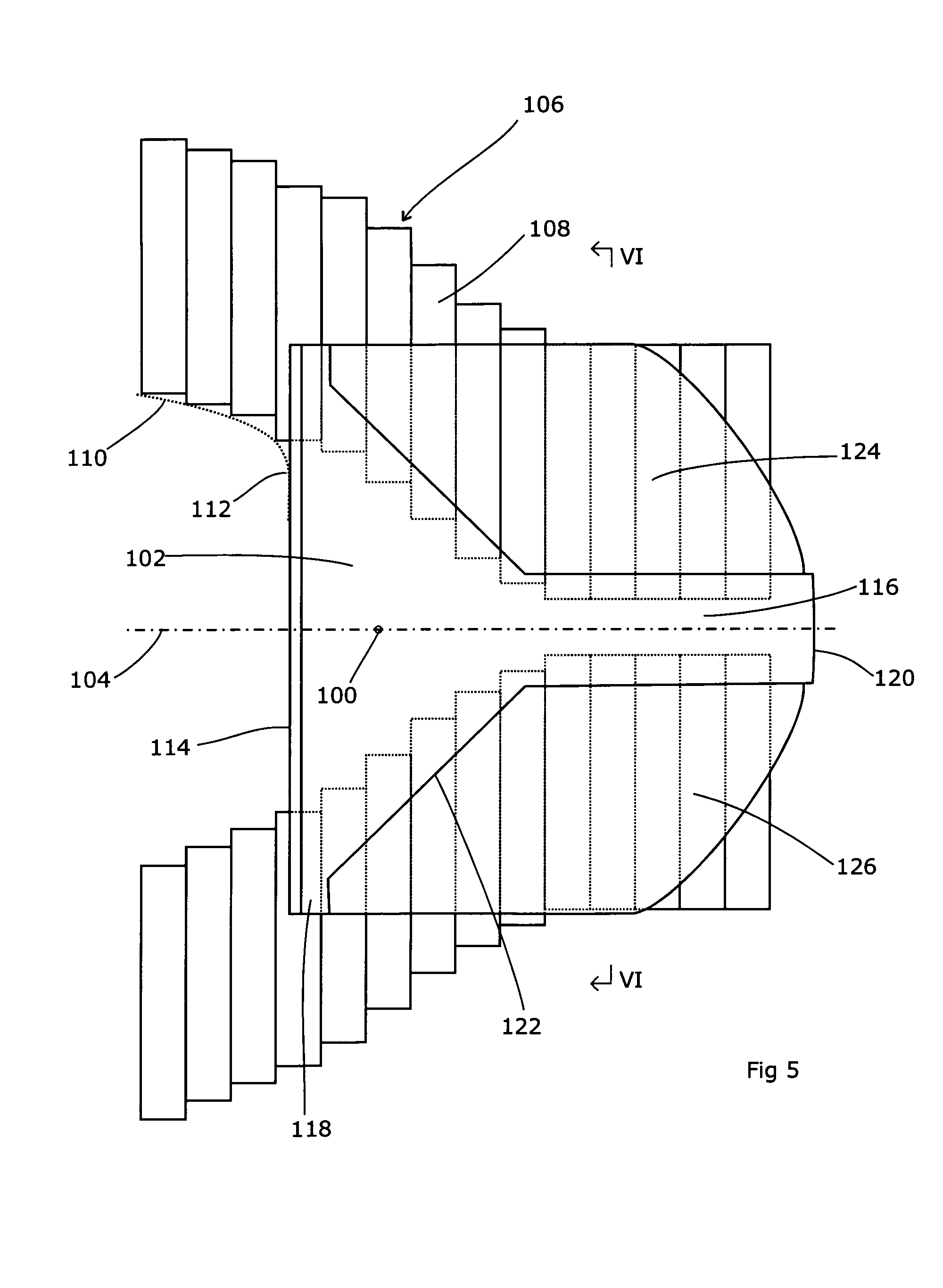
[0028]Referring to FIG. 5, showing the view along the beam axis 100, a diaphragm 102 is moveable in and out along an X axis 104 so as to selectively shield the beam to a desired degree. Only the right-hand diaphragm 102 is shown in FIG. 5; there will be a corresponding left-hand diaphragm on the other side which, in this embodiment, is of like construction although it need not be.

[0029]A multi-leaf collimator 106 operates in the Y axis. The multi-leaf collimator 106 (MLC) comprises a number of individual leaves 108 which can be extended into and out of the beam along a y axis perpendicular to the diaphragm axis 104. Each leaf can be selectively moved by a desired distance so as to shape the beam to a chosen curved outline such as that shown at 110. The extremity 112 of the curve 110 in the x axis is then met by the diaphragm 102. This both covers the inevitable small degree of leakage between the leaves 108, and allows for the possibility that the extremity 112 does not coincide wit...


PUM


Abstract

A radiotherapy apparatus comprises a means for producing a beam of radiation directed along a beam axis and having a width in first and second directions transverse to the beam axis, a multi-leaf collimator for selectively limiting the width of the beam in at least the first direction, a block collimator for selectively limiting the width of the beam in at least the second direction, the block collimator comprising a diaphragm moveable into and out of the beam and having a thickness in the direction of the beam axis that varies. The diaphragm can have a front edge of greater thickness than at least one region behind the front edge. It can also have a spine region extending from a rear part thereof towards the front edge that is greater thickness than at least one region displaced laterally with respect thereto. Together, these can cover the areas that will not be fully shadowed by a dynamically moving MLC. A control means for the multi-leaf collimator can be arranged to extend leaves of the multi-leaf collimator to shadow regions of the beam that are blocked by a relatively thinner section of the diaphragm. This is made easier if the spine region extends from the rearmost part of the diaphragm, the spine region extends to the front edge of the diaphragm, the spine region is straight, the spine region is a central region of the diaphragm, and if the width of the spine region increases towards the front edge of the diaphragm. The present invention also relates to a radiotherapy apparatus comprising a multi-leaf collimator and a block collimator, the block collimator comprising a diaphragm with variable thickness, and to a block collimator for use in radiotherapy apparatus comprising a diaphragm moveable into and out of a beam, and having a thickness in the direction of the beam axis that varies.

Description

[0001]This Application is a Section 371 National Stage Application of International Application No. PCT / EP2007 / 004625, filed May 24, 2007 and published as WO 2008 / 141667 A1 on Nov. 27, 2008, the content of which is hereby incorporated by reference in its entirety.FIELD OF THE INVENTION[0002]The present invention relates to collimation apparatus for radiotherapy.BACKGROUND ART[0003]The technique of radiotherapy involves directing a beam of harmful high-energy radiation towards a tumour. The radiation causes damage to the tumour cells which, over time, destroys the cancer. As the beam is harmful, it is necessary to limit the radiation dose that is applied to the healthy tissue, whilst at the same time maintaining the dose delivered to the tumour. Accordingly, some means needs to be provided to de-limit the radiation beam so that its size is no larger than is necessary or achievable. Early radiotherapy machines used a collimation system as shown schematically (along the beam's eye view...

Claims


Application Information

Patent Timeline
Patent Type & Authority Applications(United States)
IPC IPC(8): G21K1/04G21K1/02
CPCA61N5/1042G21K1/04G21K1/046
Inventor PERKINS, CLIFFORD WILLIAMKNOX, CHRISTOPHER CHARLES
Owner ELEKTA AB
Why Eureka
Try Eureka