
Repeated Evaporation Garment Steamer

Active Publication Date: 2010-07-01
XU WANQUN
View PDF6 Cites 16 Cited by
  • Summary
  • Abstract
  • Description
  • Claims
  • Application Information

AI Technical Summary

Benefits of technology

[0004]This invention is to solve the obvious condensation phenomenon when the steam passes a long duct due to the aforesaid defects of existing products, which greatly reduces the outlet temperature and pressure of steam and leads to low ironing efficiency and poor effect of mites elimination, and to provide a garment steamer product adopting multiple evaporation, which can basically solve the problem of condensation and provides high temperature, high pressure and low humidity at the outlet of steam so as to truly improve the ironing efficiency and effect of mites elimination of products of the same and to meet the requirements of fashion stores, small clothing factories and some families to for direct ironing of hung garments, improve people's dressing standard and effectively extend the longevity of garment fibers.
[0006]As an improvement, said first vaporizing device and said second vaporizing device use the same electric heating source to simplify the structure and reduce the cost.
[0016]When the steam with high humidity carrying a few small liquid drops enters the vaporizing chamber at the side of the second vaporizing device with said concave cavity, it can only goes forwards by swinging along the steam guiding opening on the top of said stop boards, due to the double effect of the centrifugal force and gravity, small liquid drops mixed in the steam will either be thrown onto walls of said vaporizing chamber or drop down to the bottom of said vaporizing chamber for the second vaporization and then goes towards the third vaporizing steam inlet along with the steam. Due to the effect of the second vaporizing device, steam exported from said second vaporizing steam outlet has been provided with high purity, low humidity and the temperature as high as 180˜220° C.After entering said third vaporizing steam inlet, the steam from said steam duct will rotate anticlockwise under the guiding effect of said baffle liner and then go directly leftwards, and then enter said baffle liner after another rotation anticlockwise, and finally, it will be sprayed from multiple steam nozzles. During the course of rotation, the steam is heated by said vaporizer and its temperature will rise to 170˜190° C. as set by said temperature controller, which prevents the purity and temperature of steam sprayed from said multiple steam nozzles from declining.
[0018]Compared with existing kettle type garment steamers, this product effectively overcomes the defect of obvious condensation and return flow inside the steam duct, effectively ensures the purity and temperature of steam sprayed from said brush head, greatly improves the ironing efficiency and the effect of sterilization and mites elimination, moreover, it has the advantages of novel concept, rational structure, low energy consumption and high reliability and can meet the requirements of fashion stores, small clothing factories and some families with high requirements for dressing.

Problems solved by technology

However, applicant of this patent has found through researches that due to the heating device inside the product, the steam duct and the steam nozzle are connected to the atmosphere, although the steam is vaporized again before being sprayed from the nozzle, the steam generating device still adopts the structure of a kettle, thus, condensation is still unavoidable when the steam passes a long duct; Although the humidity of the steam is lowered, its temperature and pressure are also reduced, therefore, this product still fails to improve the low ironing efficiency and poor effect of mites elimination of most garment steamers.

Method used


Image

  • Repeated Evaporation Garment Steamer
  • Repeated Evaporation Garment Steamer
  • Repeated Evaporation Garment Steamer

Examples


Embodiment Construction

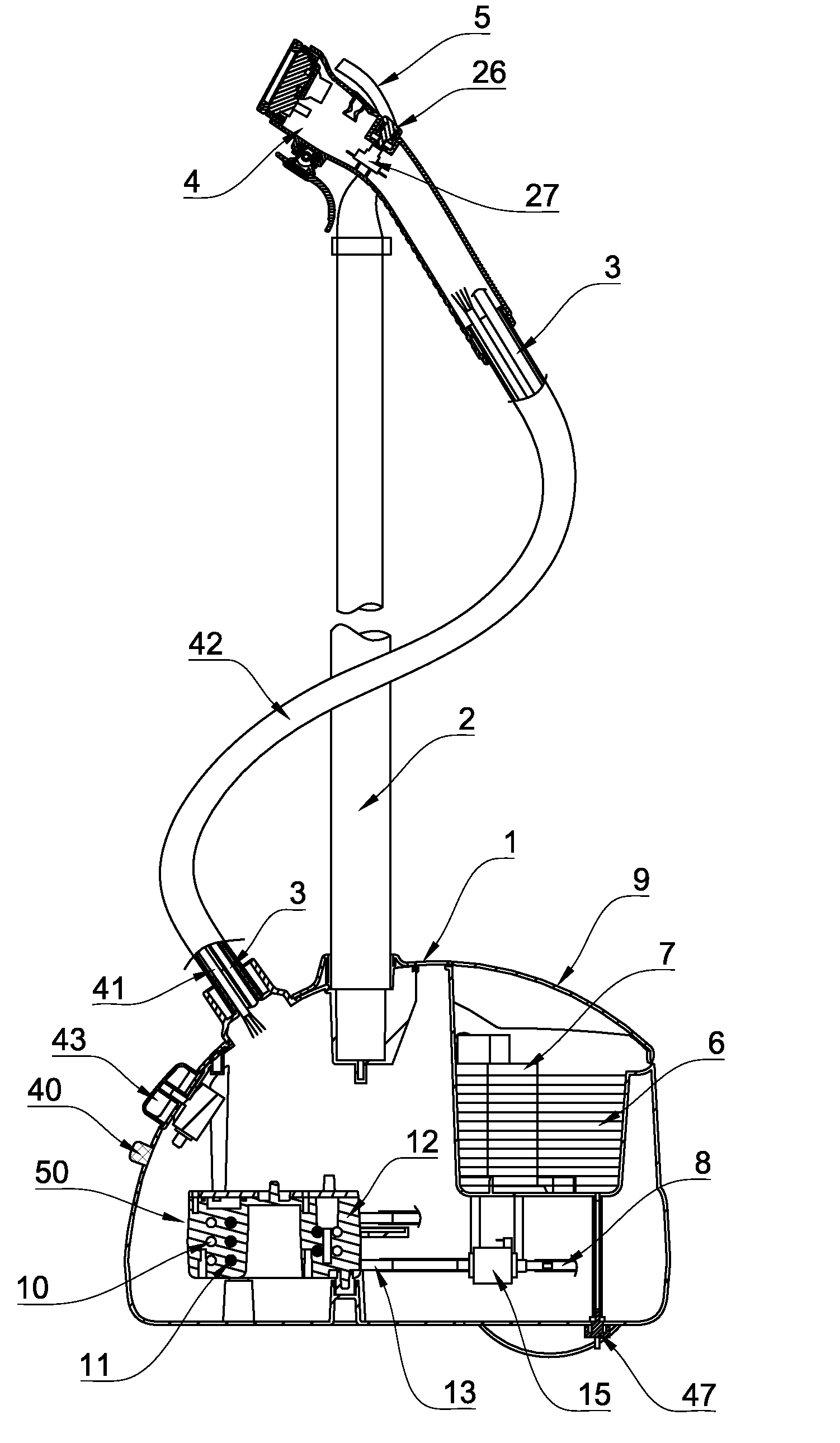
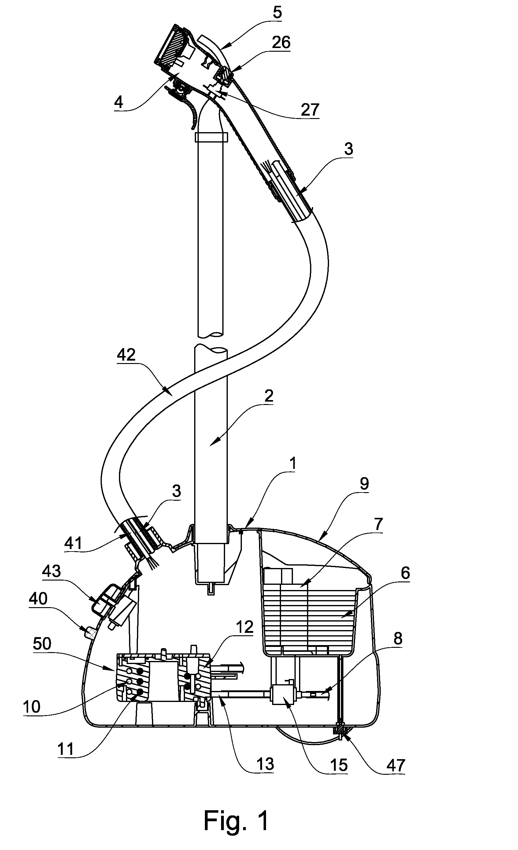
[0029]As shown in FIG. 1, this invention comprises a standing movable main body 1, a vertical supporting pole 2, a flexible steam duct 3 and a brush head 4 mounted on the head of said steam duct, a block fork 5 is provided on top of said supporting rod 2 for placing said brush head 4; the steam duct 3 and the control cables 41 of the brush head 4 are enclose by the protective hose 42. Said main body 1 is provided with a water tank 6 and a heating and vaporizing device 50, said water tank 6 is provided with the filter device 7, which is provided with the water outlet pipe 8 and the evacuation device 47; corresponding to the opening of said water tank 6, said main body is provided with the water tank cover 9. The heating and vaporizing device 50 inside said main body 1 comprises the first vaporizing device and the second vaporizing device, said first vaporizing device adopting the patented utility model technology named “Real-time steam supply steam generator for electric irons”, for ...


PUM


Abstract

This invention discloses a kind of garment steamer technology, which overcomes the defects of obvious condensation and return flow inside the steam duct and the low purity and temperature of steam. It comprises a main body, a steam duct and a brush head, being equipped with a water tank and a heating and vaporizing device inside, said heating and vaporizing device inside said main body comprising the first vaporizing device and the second vaporizing device, said brush head being equipped with the third vaporizing device; said first vaporizing device comprising a spiral vaporizing tube, an electric heating tube and a metal die cast; is provided with a water outlet pipe on the bottom, said water outlet pipe is connected with the water inlet of said spiral vaporizing tube via the pump. This product is featured by that the steam from said second vaporizing steam outlet has been provided with high purity and low humidity; after passing the third vaporizing device, the steam can be provided with guaranteed purity and temperature when being sprayed from the brush head, which greatly improves the ironing efficiency and effect of mites elimination and can be widely used in fashion stores, small clothing factories and some families with high requirements for dressing.

Description

CROSS REFERENCE TO RELATED PATENT APPLICATION[0001]The present application claims the priority of the Chinese patent application No. 200810189891.1 filed on Dec. 31, 2008, which application is incorporated herein by reference.FIELD OF THE INVENTION[0002]This invention relates to a technology to produce a kind of garment steamer, and more specifically a technology for the evaporation device of a garment steamer.BACKGROUND OF THE INVENTION[0003]Unlike ordinary electric iron products, a garment steamer can be used for direct ironing on garments hanging on the rack, which ignored the trouble of ordinary iron that an ironing board is necessary. When ironing, the steam from the brush head passes though fibers of the ferment and eliminates crimples on the surface, making the garment natural and level; in the meanwhile, strange odors, bacteria and mites are also eliminated due to the high-temperature steam, therefore it is widely used in fashion shops, small clothing factories and some fami...

Claims


Application Information

Patent Timeline
IPC IPC(8): D06B1/12F22B1/28D06B21/02
CPCD06F73/00D06F75/12F22B1/28
Inventor XU, WANQUNLI, QILIN
Owner XU WANQUN
Features
  • Generate Ideas
  • Intellectual Property
  • Life Sciences
  • Materials
  • Tech Scout
  • Unparalleled Data Quality
  • Higher Quality Content
  • 60% Fewer Hallucinations
Learn More