Scroll type fluid machine

Active Publication Date: 2010-07-01
HITACHI IND EQUIP SYST CO LTD
View PDF4 Cites 12 Cited by
  • Summary
  • Abstract
  • Description
  • Claims
  • Application Information

AI Technical Summary

Benefits of technology

[0021]In accordance with the present invention, it is possible to reduce the ce

Problems solved by technology

Accordingly, for example, when the orbiting scroll carries out a orbiting motion at a high speed, an excessive centrifugal force acts on the auxiliary crank mechanism, and there is a risk that a durability of the auxiliary crank mechanism is lowered.
However, in the structure of the patent document 1, since the annular elastic member is provided between the main bearing and t

Method used


Image

  • Scroll type fluid machine
  • Scroll type fluid machine
  • Scroll type fluid machine

Examples


first embodiment

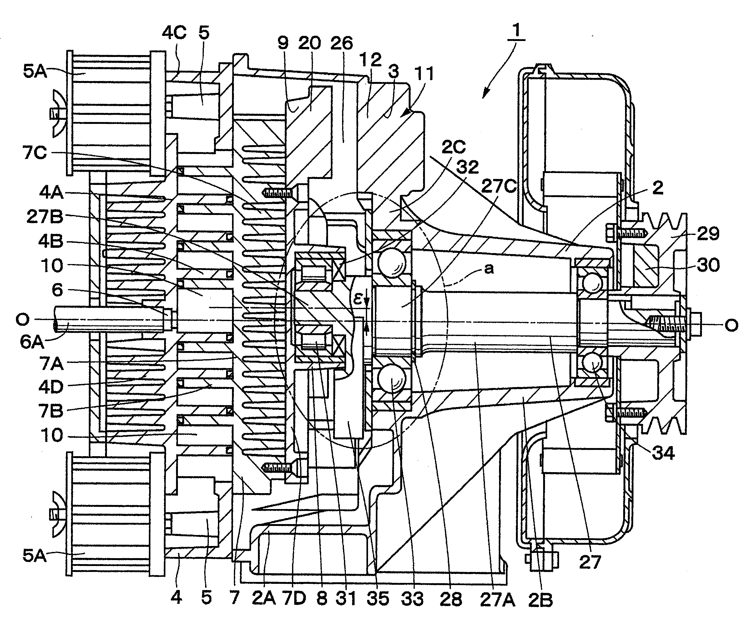
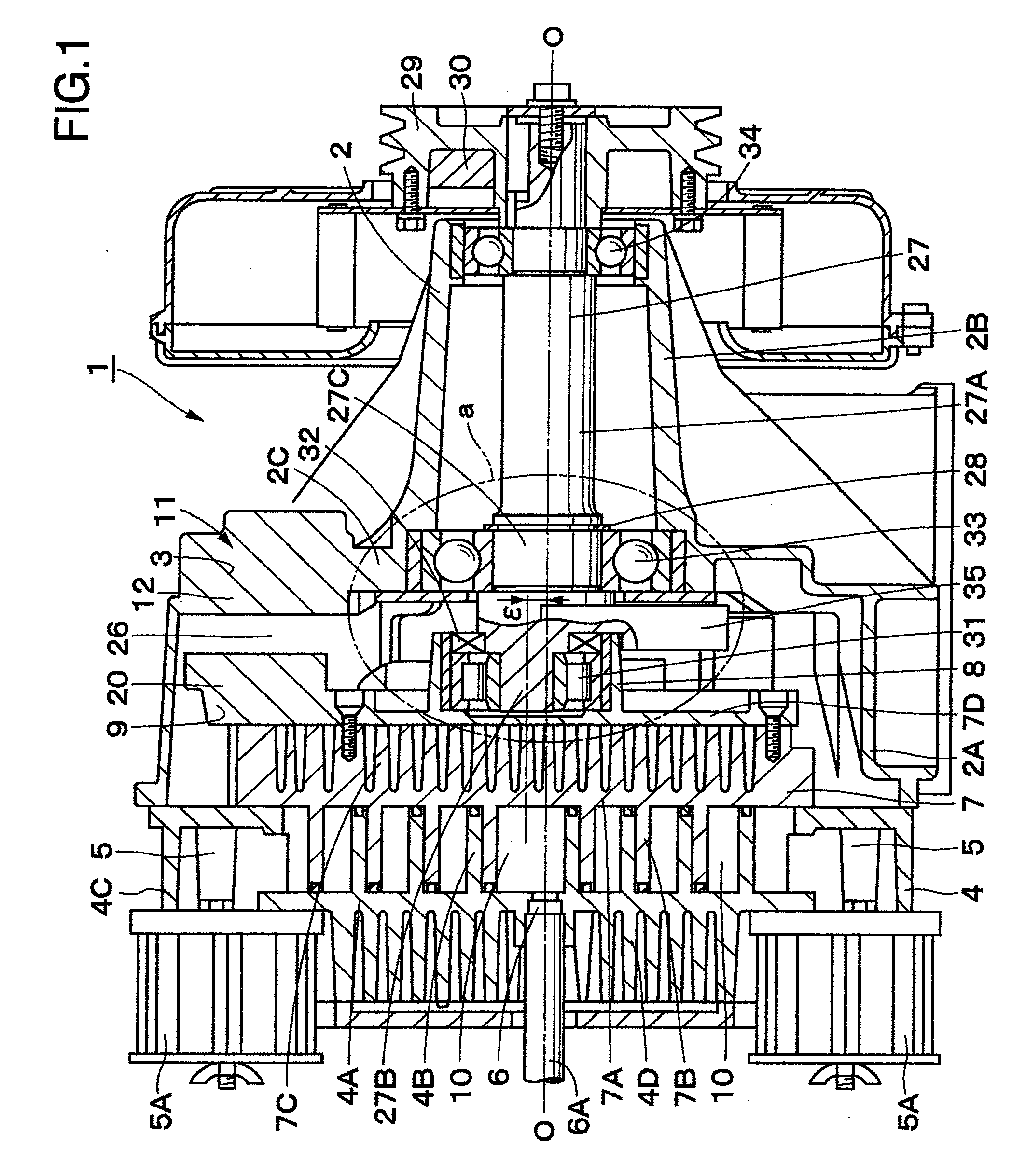
[0043]First of all, FIGS. 1 to 7 show a first embodiment in accordance with the present invention. In FIG. 1, reference numeral 1 denotes a scroll type air compressor compressing an air. The scroll type air compressor 1 is roughly constructed by a casing 2 mentioned below, a fixed scroll 4, a orbiting scroll 7, an auxiliary crank mechanism 11, a drive shaft 27 and the like.

[0044]Reference numeral 2 denotes a casing forming an outer frame of the scroll type air compressor 1. The casing is formed as a stepped tubular body in which one side in an axial direction is approximately closed, and the other side is open. Further, the casing 2 is roughly constructed by a large-diameter tube portion 2A, a small-diameter bearing tube portion 2B which is formed as a tubular shape having a smaller diameter than the large-diameter tube portion 2A and protrudes outward from one side in an axial direction of the large-diameter tube portion 2A, and an annular portion 2C which is formed between the bea...

second embodiment

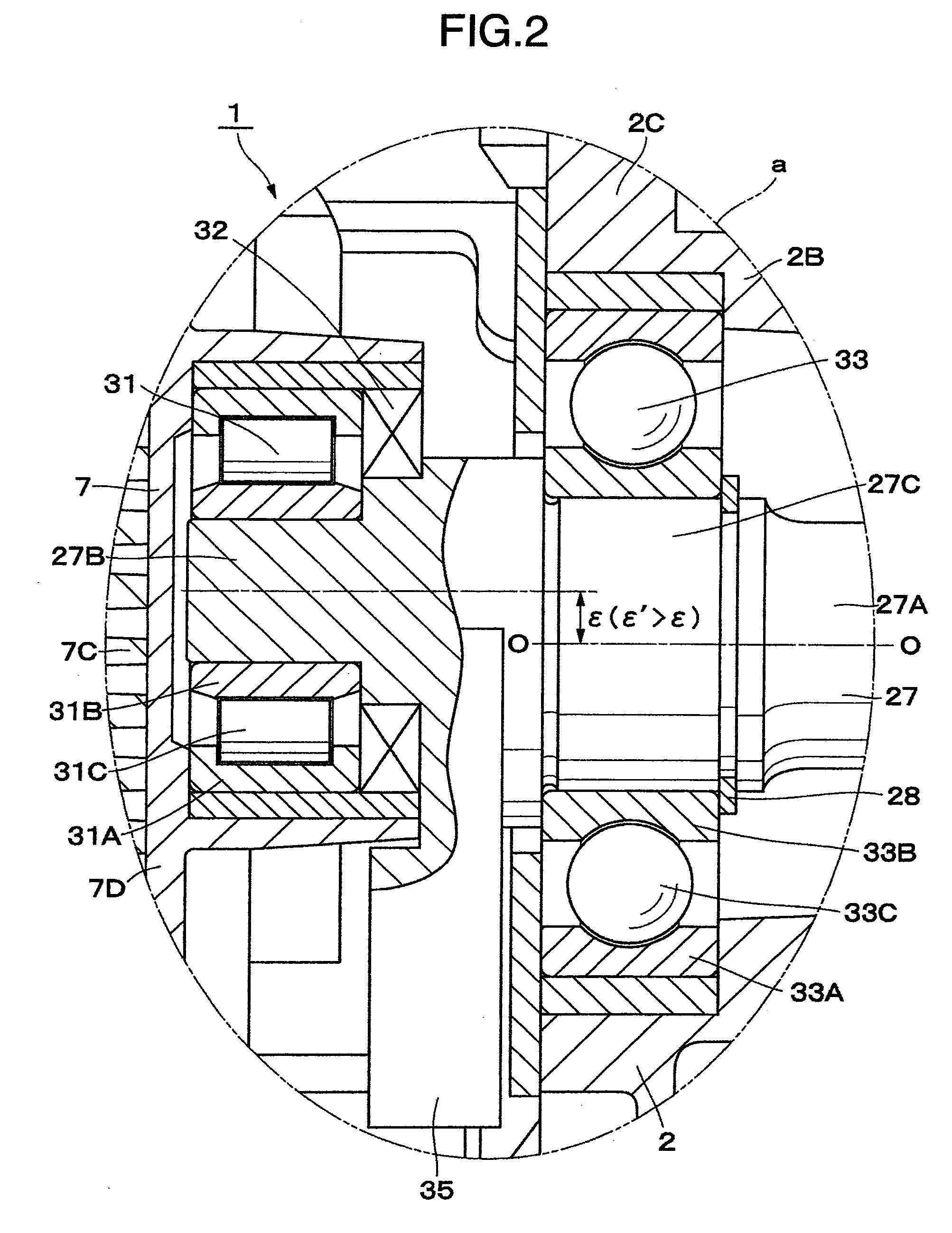
[0135]The scroll type air compressor 1 in accordance with the second embodiment has the structure as mentioned above. Next, the applicant makes a study of a relation between the internal gap δa of the orbiting bearing 53 and the internal gap δb of the main bearing 54, and the load caused by the centrifugal force received by the auxiliary crank mechanism 11.

[0136]First of all, the applicant makes a study of a case that an internal gap δa of a orbiting bearing 62 is larger than an internal gap δb of a main bearing 63 (δa>δb) such as a compressor 61 in accordance with a second comparative example shown in FIGS. 15 to 17. At this time, it is assumed that the eccentric amount ε of the drive shaft 52 is set to the same value as the eccentric amount ε′ of the auxiliary crank shaft 26 (δ=ε′).

[0137]If the operation of the compressor 61 in a stop state as shown in FIG. 15 is started, the drive shaft 52 is rotationally driven, and the orbiting scroll 7 starts its orbiting motion. At this time,...


PUM


Abstract

The invention reduces a centrifugal force of a orbiting scroll which acts on an auxiliary crank mechanism. A crank pin which is eccentric from a main shaft portion is formed in a drive shaft, and a main balance weight is provided in a base end side of the crank pin. The main shaft portion of the drive shaft is rotatably supported by using a main bearing, and the crank pin is attached to a orbiting bearing which is provided in a back face side of a orbiting scroll. Further, an internal gap of the main bearing is set to a value which is larger than a value obtained by subtracting the double value of an eccentric amount difference between an eccentric amount of an auxiliary crank shaft and an eccentric amount of the drive shaft from an internal gap of the orbiting bearing. Accordingly, the internal gap of the main bearing does not come to 0 even if a compressor comes to a steady state.

Description

INCORPORATED BY REFERENCE [0001]The present application claims priority from Japanese application JP2008-332724 filed on Dec. 26, 2008, the content of which is hereby incorporated by reference into this application.BACKGROUND OF THE INVENTION [0002]The present invention relates to a scroll type fluid machine which is preferably employed in a compressor of a fluid, for example, an air or the like, a vacuum pump, an expansion machine and the like.[0003]Generally, as a scroll fluid machine, there are a compressor compressing a fluid such as an air, a refrigerant or the like, a vacuum pump depressurizing an internal side of a container, an expander expanding the fluid and the like. This kind of scroll type fluid machine is provided with a fixed scroll which is fixed to a casing and is provided in a rising manner with a spiral wrap portion in a surface of a end plate, a orbiting scroll which is provided in a rising manner with a spiral wrap portion in a surface of a end plate and defines...

Claims


Application Information

Patent Timeline
IPC IPC(8): F01C1/02
CPCF01C21/02F04C18/0215F04C29/0057F04C2230/605F04C2240/807
Inventor IWANO, KIMINORISUEFUJI, KAZUTAKAHARASHIMA, TOSHIKAZU
Owner HITACHI IND EQUIP SYST CO LTD
Why Eureka
Try Eureka