
Method of using mask film to form relief images

a mask film and relief image technology, applied in thermography, instruments, photosensitive materials, etc., can solve the problems of difficult to achieve higher sensitivity, difficult to achieve high sensitivity, and high level of halation of printed images, and achieve good reverse line depth

Active Publication Date: 2010-07-01
MIRACLON CORP
View PDF9 Cites 14 Cited by
  • Summary
  • Abstract
  • Description
  • Claims
  • Application Information

AI Technical Summary

Benefits of technology

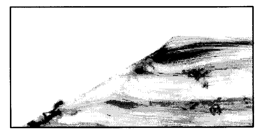
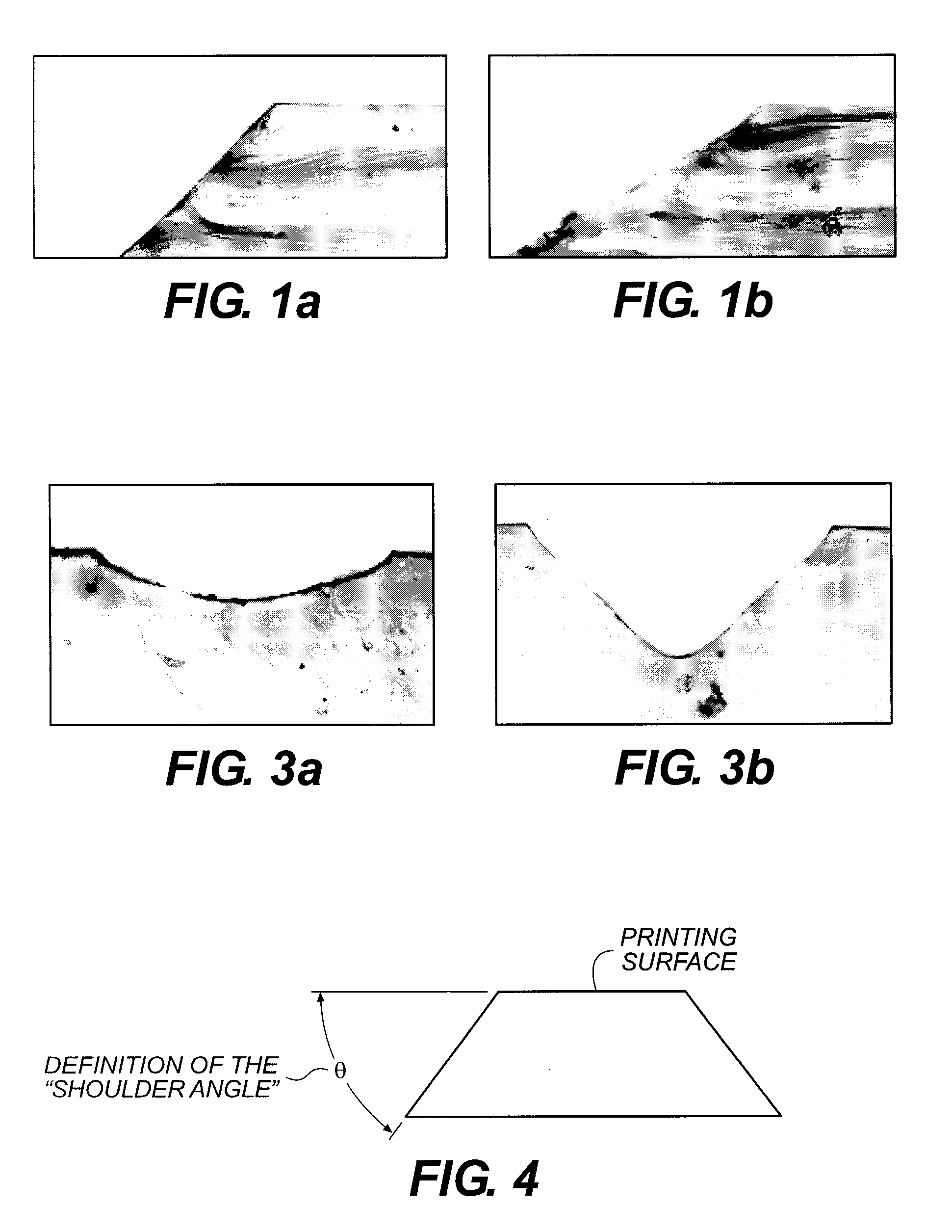
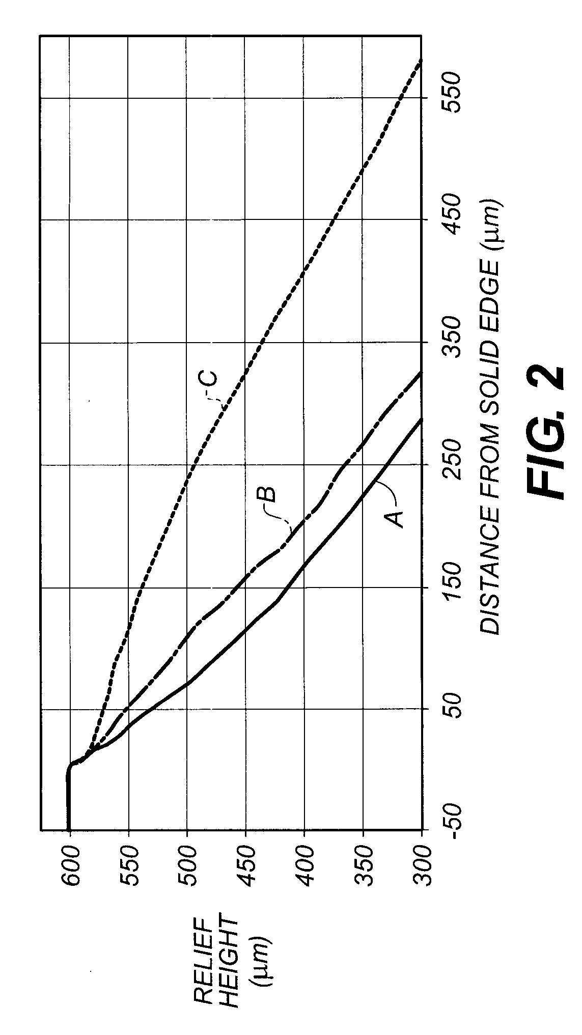
[0033]The present invention provides an improved mask-forming film and method of using it to provide imaged radiation-sensitive elements (such as flexographic printing plates) with improved relief images that predominantly have shoulder angles of at least 50° while holding desired small dot features in halftone areas and maintaining good reverse line depth.
[0034]When the imaged film (masking film) is used to form a relief image in a radiation-sensitive element, the imaged film is placed into intimate or complete optical contact with the element in such a manner as to eliminate any air, void space, or gap at the interface (thus, an “air-free” interface). Such a gap may be under vacuum so that air is lacking, but such a gap under vacuum also would not be considered an “air-free” interface.
[0035]The unique film of the present invention also provides a modified path for incident relief-forming radiation at the air-free interface during exposure through the mask so that incident radiation light is properly bent to enter the radiation-sensitive element at a desired angle to provide a steeper shoulder angles or slopes around the edges of imaged areas in the resulting relief image.

Problems solved by technology

While flexographic printing plates having an integral laser-ablatable mask layer allow direct imagewise exposure using a laser and do not require a separate masking device, the time for imaging is generally too long since the system sensitivity to imaging radiation is low.
However, obtaining higher sensitivity has been a challenge due to the widely varying quality criteria that must be simultaneously satisfied.
This results in a higher level of halation of the printed image.
However, the over-exposure fills in the reverse lines or shadow areas.
Thus, over-exposure results in image quality degradation.
Halos lead to degradation in the print quality of flexographic printing plates and are linked to dot-gain that is the formation of a larger image dot size than intended.
Another cause of halation is the presence of low-angle-of incidence radiation during exposure that can enter the photopolymer below the mask at the edges of exposed areas, reducing the shoulder angles.
As the average shoulder angle decreases below 50°, the loss in the relief sharpness becomes increasingly noticeable and as the average shoulder angle decreases below 40° there is a considerable loss in print stability and sharpness.
However, a collimated light source is more expensive to use than commonly used point light or bank light source.

Method used


Image

  • Method of using mask film to form relief images
  • Method of using mask film to form relief images
  • Method of using mask film to form relief images

Examples


invention example 3

[0201]Transparent layer formulations were prepared using the components shown in the following TABLE V and then used to prepare film samples.

TABLE VFilm Sample 1Film Sample 2Film Sample 3FormulationFormulationFormulationFormulationComponent(% solids)(% solids)(% solids)Airvol ® 205908478polyvinyl alcoholPEG 600101010polyethylene glycolNaBF40612n-Propanol20 parts20 parts20 partsWater80 parts80 parts80 partsPEG 600 and NaBF4 are available from Aldrich Chemical Company.

[0202]Each of the film samples above were prepared by coating the transparent layer formulations shown in TABLE V and onto 4 mil (0.01 cm) poly(ethylene terephthalate) support (carrier sheet) using a #26 wound-wire coating rod. The resulting transparent layers were dried at 93° C. for 2 minutes to provide a dry coverage of about 3.5 g / m2. Fully functional film constructions were prepared by coating and drying on each of these transparent layers: (i) barrier, (ii) imageable, and (iii) overcoat layers as described for Inve...


PUM

PropertyMeasurementUnit
average shoulder angleaaaaaaaaaa
refractive indexaaaaaaaaaa
thicknessaaaaaaaaaa

Abstract

A mask-forming film has a transparent layer between the imageable layer and the carrier sheet, which transparent layer has a refractive index that is lower (by at least 0.04) than that of the carrier sheet or any immediately adjacent layer between it and the carrier sheet. This lower refractive index layer modifies the path of incident radiation during mask image transfer so as to provide steeper shoulder angles in the relief image solid areas. This mask film is used to form a relief image such as in a flexographic printing plate.

Description

CROSS-REFERENCE TO RELATED APPLICATION[0001]This is a Divisional of pending application Ser. No. 11 / 758,042, filed Jun. 5, 2007.FIELD OF THE INVENTION[0002]This invention relates to a film or element in which a mask image can be formed that then can be used to form an imaged element bearing a relief image. In particular, this invention relates to mask-forming films that are readily useful for preparing flexographic printing plates, and to methods of making such plates.BACKGROUND OF THE INVENTION[0003]Radiation-sensitive elements having a laser-ablatable mask layer on the surface are known in the art. A relief image can be produced in such elements without the use of a digital negative image or other imaged element or masking device. Films with a laser-ablatable mask layer can be formed by first imagewise exposing the film with laser radiation (generally an infrared radiation laser under computer control) to selectively remove the mask layer in the exposed areas. The masking film is ...

Claims


Application Information

Patent Timeline
Patent Type & Authority Applications(United States)
IPC IPC(8): G03F7/20G03F1/92
CPCB41C1/05B41M5/40G03F1/68Y10T428/24942G03F7/202Y10S430/145G03F7/2014
Inventor ZWADLO, GREGORY L.BROWN, DAVID E.FOHRENKAMM, ELSIE A.STOLT, A. PETER
Owner MIRACLON CORP
Learn More