
Washing apparatus

a technology of washing apparatus and impeller, which is applied in the field of apparatus, can solve the problems of reducing the outlet pressure of the impeller, affecting the productivity and the effectiveness of the wash, and affecting the efficiency of the wash, so as to avoid the risk, avoid the effect of exploitation and effective washing

Inactive Publication Date: 2010-07-08
STEELCO
View PDF23 Cites 12 Cited by
  • Summary
  • Abstract
  • Description
  • Claims
  • Application Information

AI Technical Summary

Benefits of technology

[0035]Moreover, the present invention does not produce any interference of the hydraulic pipe with the distribution elements, particularly in the variant with the impellers, allowing to size them correctly, thus increasing productivity and the effectiveness of the wash.
[0037]The present invention also avoids the risk of leakages of treatment fluid to the floor surrounding the washing apparatus.
[0038]Since the hydraulic connection pipe directs the treatment fluid downwards, there is no contrast to the force of gravity and there is an effective exploitation of most of the treatment fluid in the delivery element, with optimum outlet pressure to the distribution elements and effective washing.
[0040]Furthermore, there is no need for a counter-thrust element or member, on the side opposite the one where said hydraulic pipe is connected, to prevent the trolley from moving or overturning once the pipe is connected. The vertical force of hydraulic coupling between the connection pipe and the connector element has the bottom of the washing chamber as a natural contrast.
[0041]An advantageous variant of the invention provides that the connector element is in a central position with respect to the secondary distribution circuit of the frame. This allows a uniform distribution of the treatment fluid in the secondary distribution circuit of the trolley, with a consequent homogeneity of the outlet pressure of the treatment fluid to the distribution elements, and a greater efficiency of the wash.

Problems solved by technology

interference of the hydraulic pipe with the impellers, which are thus eliminated or reduced in diameter, but to the detriment of productivity and the effectiveness of the wash;
risk of leakages of washing liquid from the lower compartment to the floor around the washing apparatus;
reduced exploitation of most of the washing liquid in the delivery element, due to the contrasting action of the force of gravity during the thrust from the bottom upwards, with reduced outlet pressure to the impellers and possible inefficiency of the wash.
risk of lateral interference with the baskets or the impellers;
unequal distribution of the washing liquid in the secondary distribution circuit of the trolley, due to the lateral position of the delivery element, with consequent lack of homogeneity in the outlet pressure of the washing liquid to the impellers and possible inefficiency of the wash.

Method used


Image

  • Washing apparatus
  • Washing apparatus
  • Washing apparatus

Examples


Embodiment Construction

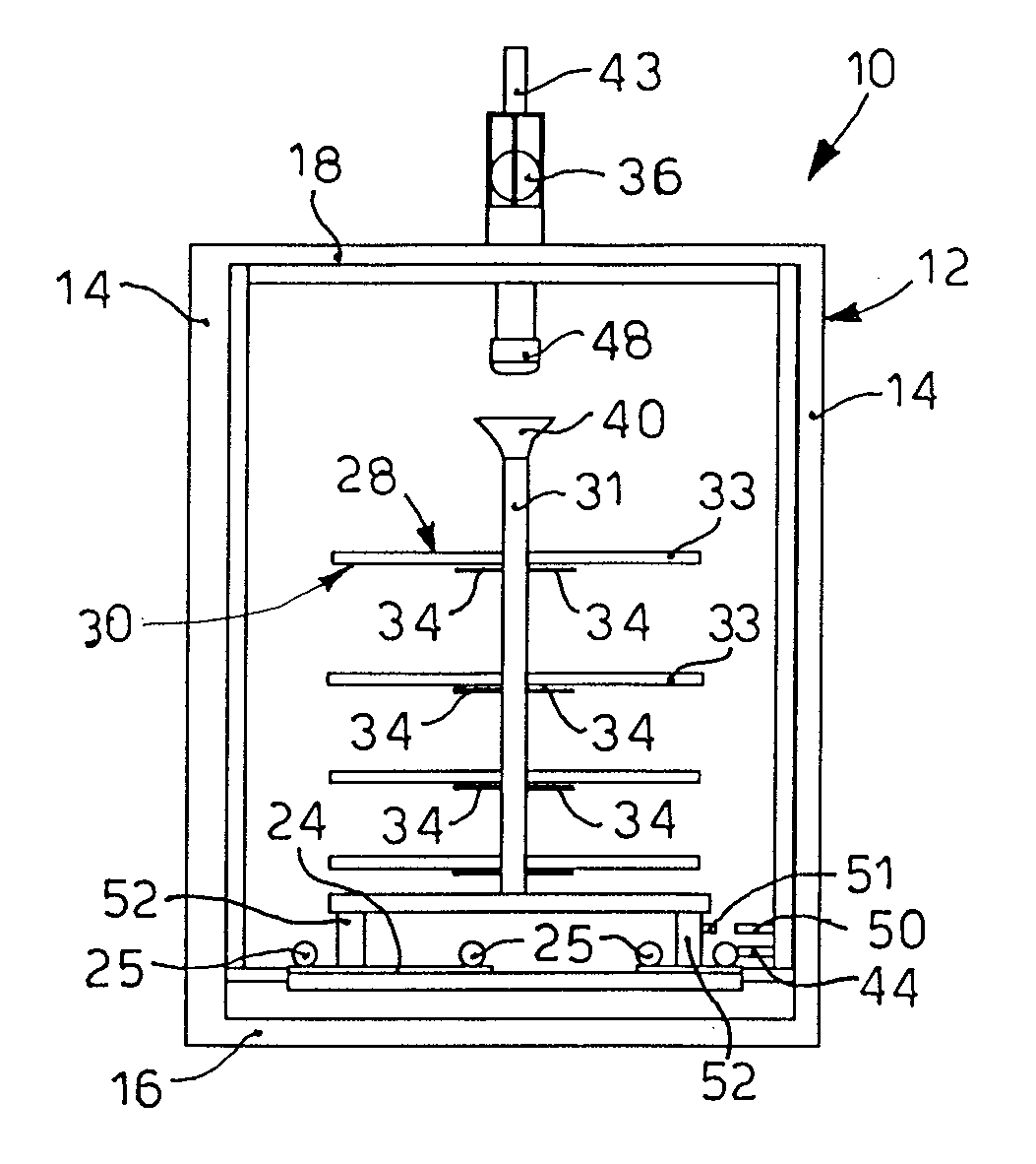
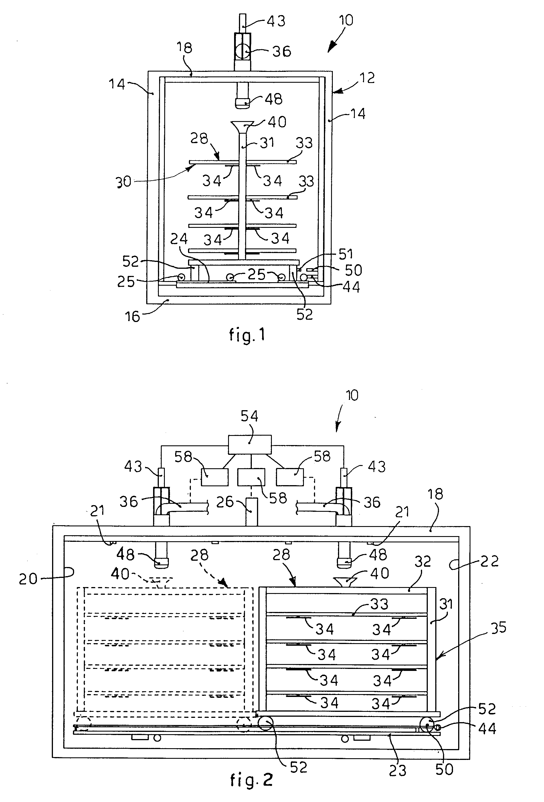
[0046]With reference to FIG. 1, a washing apparatus 10 according to the present invention comprises a washing chamber 12 suitable for washing and heat-disinfecting surgical instruments of a known type and not shown in the drawings.

[0047]The washing chamber 12 is of the oblong tunnel type and is delimited by two lateral walls 14, a bottom wall 16 and an upper wall 18, and is also provided with access apertures 20, 22, closed by means of doors of a known type and not shown in the drawings, for example of the sliding type. A first aperture 20, disposed on the front side (FIG. 2), is used for access to the washing chamber 12 from the “dirty” side, that is, before washing.

[0048]A second aperture 22, disposed on the rear side, is used for outlet from the washing chamber 22 on the clean side.

[0049]On the bottom wall 16 a support plane 23 is also fixed, inclinable laterally and provided with two parallel runners 24 delimited by respective guide bars 25. The runners 24 are suitable for the s...


PUM


Abstract

Washing apparatus includes a washing chamber having two lateral walls, bottom wall and upper wall, and at the front an aperture for inlet and / or outlet; a main distribution circuit to distribute treatment fluid inside the chamber; a trolley-type movement device, insertable into the chamber, including a frame to support objects to be subjected to a washing cycle in the chamber and on which treatment fluid distribution elements are mounted. The frame formed by hollow tubular elements functioning as a secondary distribution circuit of washing liquid towards the distribution elements; a connector element located on a frame upper part as a secondary distribution circuit delivery element; and a hydraulic connection pipe mounted on the upper wall, to connect hydraulically the main distribution circuit to the secondary distribution circuit connector element, selectively movable vertically between a first position connected to the connector element and a second position separate from the connector element.

Description

FIELD OF THE INVENTION[0001]The present invention concerns an apparatus for washing trolley-type objects, for example trolleys, beds and other wheeled equipment, and objects in general disposed on trolleys, in a washing chamber, for example of the type used in the field of hospitals, or in the field of restaurants, for washing self-service trolleys, or those used in aircraft. By washing chamber, here and hereafter, we mean a chamber in which the trolley-type objects can be subjected to at least one of the following treatments which constitute a so-called washing cycle: pre-wash in cold and / or hot water, hot-water wash advantageously with detergents, rinse, disinfection by means of chemicals and / or heat-disinfection, with a possible final drying using air, hot air or other fluid.BACKGROUND OF THE INVENTION[0002]A washing apparatus is known, for washing and heat-disinfecting surgical instruments, laboratory instruments or other, contained in baskets carried by a trolley, container or ...

Claims


Application Information

Patent Timeline
Patent Type & Authority Applications(United States)
IPC IPC(8): B08B3/00
CPCA47L15/247A47L15/508A61B50/13A61B90/70B08B3/02B08B3/024
Inventor CASONATO, OTTORINO
Owner STEELCO
Features
  • Generate Ideas
  • Intellectual Property
  • Life Sciences
  • Materials
  • Tech Scout
  • Unparalleled Data Quality
  • Higher Quality Content
  • 60% Fewer Hallucinations
Learn More