Elongate composite structural members and improvements therein

a composite structural member and elongation technology, applied in the field of composite material structure, can solve the problems of complex desired shape of structural member for use when stiffening a panel, pad-up in the panel, and increase the risk of defects, so as to reduce the risk of deviation.

Inactive Publication Date: 2010-07-08
AIRBUS OPERATIONS LTD
View PDF41 Cites 39 Cited by
  • Summary
  • Abstract
  • Description
  • Claims
  • Application Information

AI Technical Summary

Benefits of technology

[0044]In embodiments of the present invention, the changes in the geometry of the spar model are advantageously generated to reduce the risk of defects being created in a spar made from layered composite material according to the spar model. For example, the shape of the spar may include a web which is oriented relative to a flange such that the angle between the web and flange varies as a function of distance along the length of the spar. The shape of the spar may be designed to reduce any deviation from a linear relationship between the distance along the length of the spar model and the distance parameter.

Problems solved by technology

Local variations in the geometry of the structural member can however introduce manufacturing problems when fabricating composite structural members.
This results in pad-ups in the panel when viewed from the interior of the wing-box.
The desired shape of structural member for use when stiffening a panel may therefore be complicated and may deviate from a linearly symmetrical geometry.
Manufacturing composite structural members having a complicated geometry can be difficult.
If local changes in cross-sectional geometry of the structural member are required, defects may be introduced during the fabrication process.
Such defects usually result from layers of fibre material being compressed or folded in regions where there is too much material in view of the local geometry.
This can produce creases in the final product, typically in the form of transverse creases.
Defects can also result from layers of fibre material being stretched and / or stressed in regions where there is too little material in view of the local geometry.
This too can produce creases in the final product, typically in the form of longitudinal creases.
Either of the foregoing types of defect (too little material or too much material) can result in undesirable weakening of, and / or localised internal stresses in, the composite material in such regions.
Whilst the strength of the resulting component may not be thus compromised, this technique introduces a weight penalty and excessive structural volume.

Method used


Image

  • Elongate composite structural members and improvements therein
  • Elongate composite structural members and improvements therein
  • Elongate composite structural members and improvements therein

Examples


first embodiment

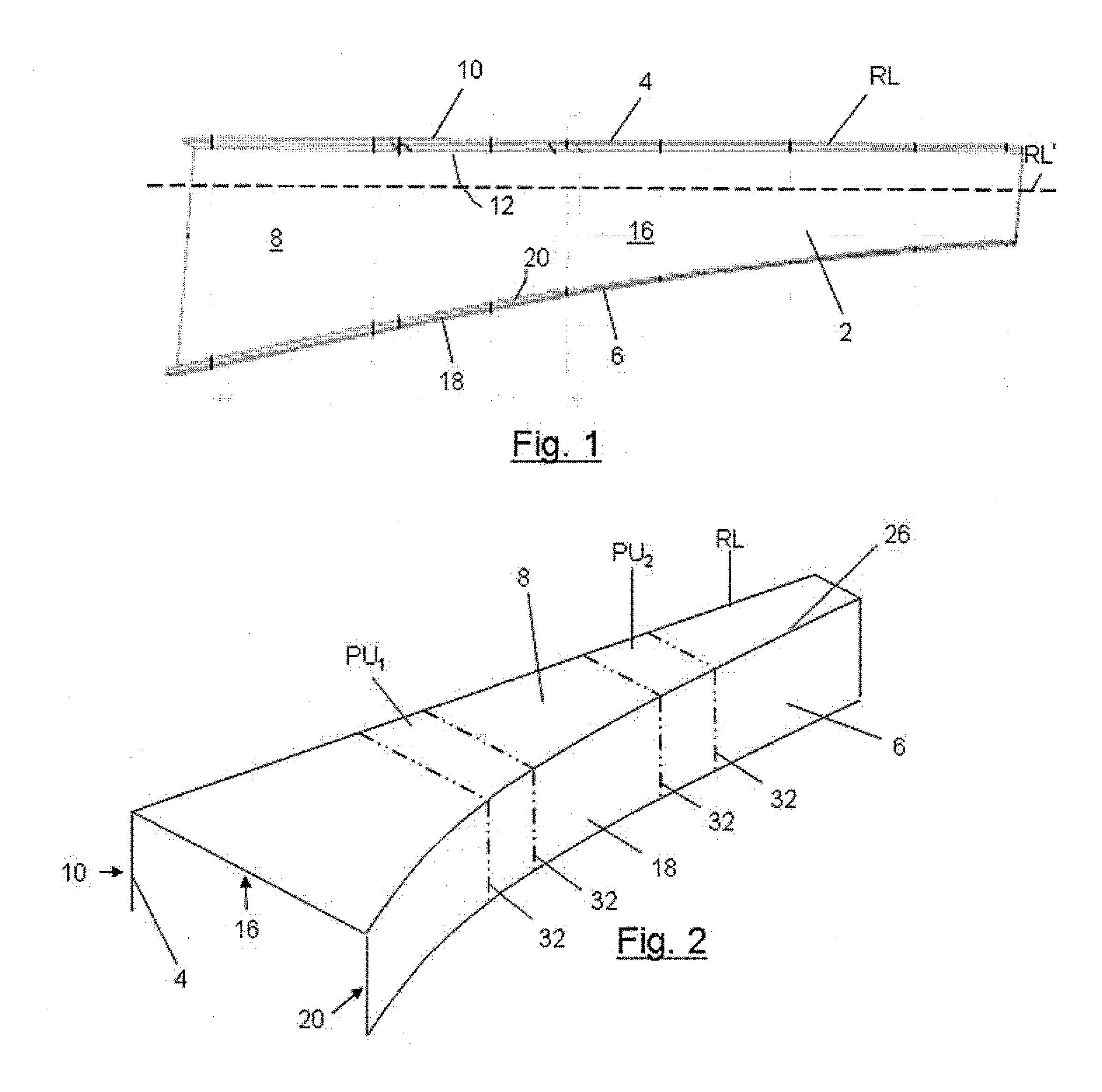
[0058]The geometry of the spar 2 is shown in FIG. 1 is designed in accordance with a method illustrated by FIGS. 2 to 11b. The method of the invention generates a geometry of spar such that:[0059](1) the first surface 10 on the upper flange 4 has a geometry that matches and corresponds to the desired geometry of the wing skin at the interface between the spar and the upper wing skin;[0060](2) the fifth surface 18 on the lower flange 6 has a geometry that matches and corresponds to the desired geometry of the wing skin at the interface between the spar and the lower wing skin; and[0061](3) the geometry of the first, third and fifth surfaces of the spar is such that its developed form is effectively a two-dimensional plane.

[0062]By ensuring that the developed form of the component is a 2-D plane, it enables the layers of fibre mats that are laid up during the hot drape forming process to be folded and manipulated to adapt to the desired geometry of the spar as defined by the inner and...

third embodiment

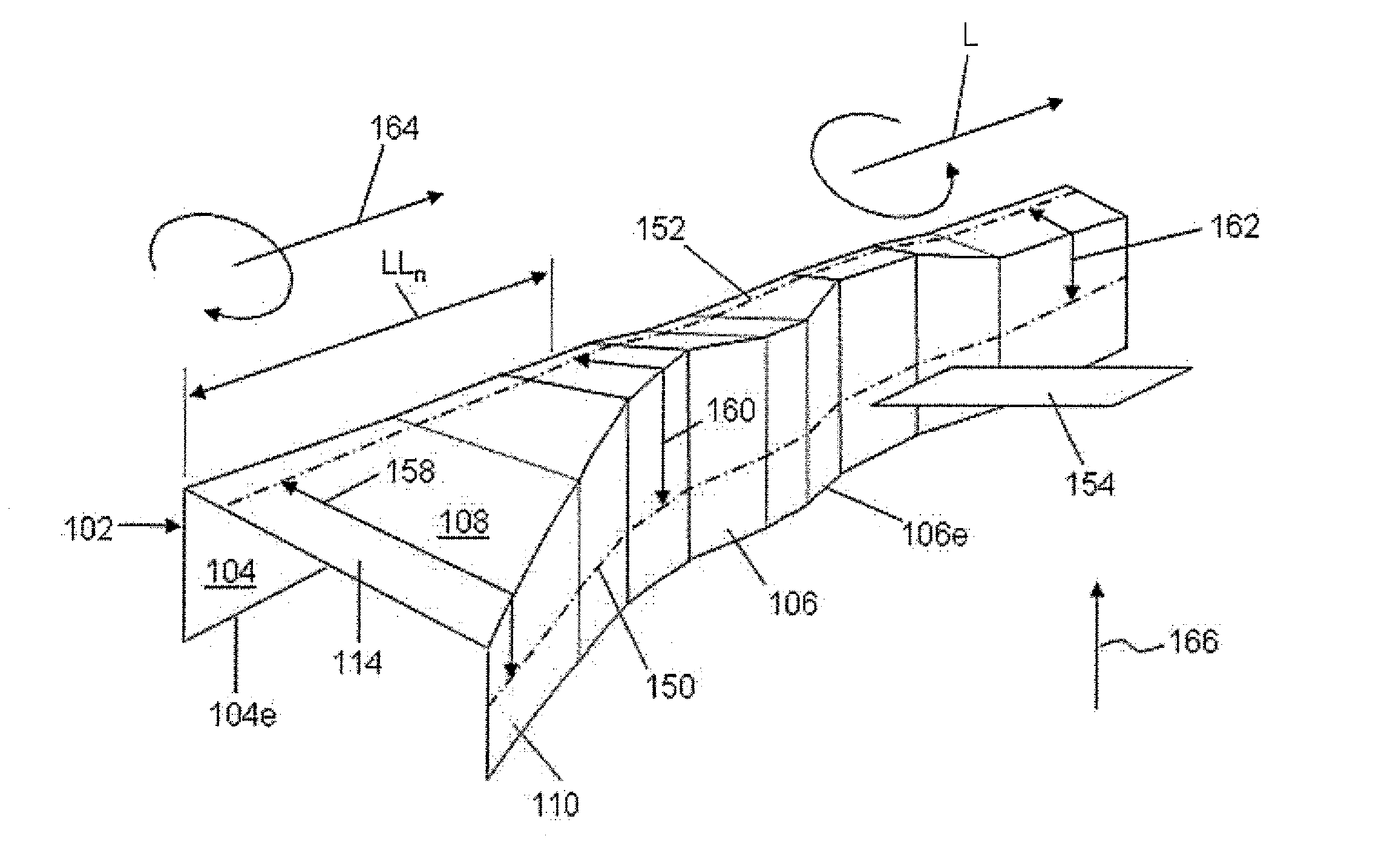
[0082]FIGS. 13a to 13d illustrate schematically a spar accordingly to the present invention. The spar 102 is made from layers of fibre material embedded in a resin matrix, the outer layer of which being shown in FIG. 13a in schematic form. Whilst there are well defined edges and boundaries in the layer shown in FIG. 13a it will be appreciated that it is not easy to form such sharp edges by means of layers of composite material. In reality there would typically be no sharp edges to the shape of the spar and instead there are smooth radii between transitions of one gradient and a different gradient. The layer shown in FIG. 13a has a first surface 110 being shaped to abut a wing panel and a second surface (not shown in FIG. 13a) opposite the first surface and being on the same (lower) flange 106. The spar also includes a web 108 which extends from the lower flange 106. On the web 108 there is defined a third surface 114 which is at the same layer in the composite material as the first ...


PUM

PropertyMeasurementUnit
angleaaaaaaaaaa
lengthaaaaaaaaaa
shapeaaaaaaaaaa

Abstract

A composite material elongate structural member, such as a spar, for use in an aerospace structure, comprises a web disposed between upper and lower flanges. The web may include a clockwise twist about an axis parallel to the length L at a first portion towards the wing-root-end of the spar and a counter-twist in the anticlockwise direction at a second portion towards the wing-tip-end of the spar. The geometry of the spar may vary non-linearly along its length (L) so that the developed width of the spar as measured from a distal edge of the upper flange via the web to a distal edge of the lower flange varies linearly with increasing distance along the length (L). The risk of causing, during fabrication of the spar, undesirable creasing, stressing or stretching of composite material layers in a region in which the geometry of the member varies non-linearly may be reduced by means of such an arrangement.

Description

TECHNICAL FIELD[0001]The present invention concerns composite material structures for use in aerospace applications. More particularly, but not exclusively, this invention concerns an elongate composite structural member, for example in the form of a composite spar, a composite rib, a composite stringer, or the like. The invention also concerns a method of designing and a method of manufacturing such an elongate composite structural member, for example with the use of a suitably programmed computer.BACKGROUND OF THE INVENTION[0002]Elongate composite structural members, such as spars, ribs, stringers and the like are typically used to provide structural support in a structure on a global or local scale. Spars and ribs for example provide the main structural framework for an aerofoil box or fuselage structure. Stringers for example are used as stiffening members.[0003]Elongate composite structural members thus have portions that are adapted to abut another component, for example to st...

Claims


Application Information

Patent Timeline
Patent Type & Authority Applications(United States)
IPC IPC(8): B64C3/18B64C1/06G06F17/50B29C70/30
CPCB29C70/30B29K2105/246B64C1/064B64C1/065B64C3/182Y02T90/50B64C3/187B64C2001/0072G06F17/5095Y02T50/43B64C3/185G06F30/15Y02T50/40Y02T90/00B29C70/302
Inventor GRAY, IAN L.
Owner AIRBUS OPERATIONS LTD
Why Eureka
Try Eureka