
Particle therapy installation

a particle beam and installation technology, applied in the field of particle beams, can solve the problems of greater cost involved in generating and steering particle beams, compared with conventional radiation methods, and achieve the effect of effective shielding and effective shielding

Inactive Publication Date: 2010-07-08
SIEMENS HEALTHCARE GMBH
View PDF15 Cites 26 Cited by
  • Summary
  • Abstract
  • Description
  • Claims
  • Application Information

AI Technical Summary

Benefits of technology

The present invention provides a particle therapy system with a simple and cost-effective way to shield treatment chambers and access areas, while still allowing for efficient space usage and easy handling of patient beds. The system includes an irradiation chamber with a radiation protection door in the access area, which ensures that radiation cannot escape from the chamber. The access area is designed with a straight path, which reduces the amount of space needed and makes it easier to move the patient bed. The radiation protection door is made from steel and has a thickness of at least 45 cm. The system may also include multiple treatment rooms with corresponding access areas, each with a radiation protection door and a straight path for easy handling of patient beds. The access area is designed to minimize the amount of radiation that reaches it from the irradiation chamber. Overall, the invention provides a more efficient and cost-effective particle therapy system with improved safety and access.

Problems solved by technology

The costs involved in generating and steering a particle beam are greater by comparison with conventional radiation methods such as, for example, with high-energy x-ray beams.

Method used


Image

  • Particle therapy installation
  • Particle therapy installation
  • Particle therapy installation

Examples


Embodiment Construction

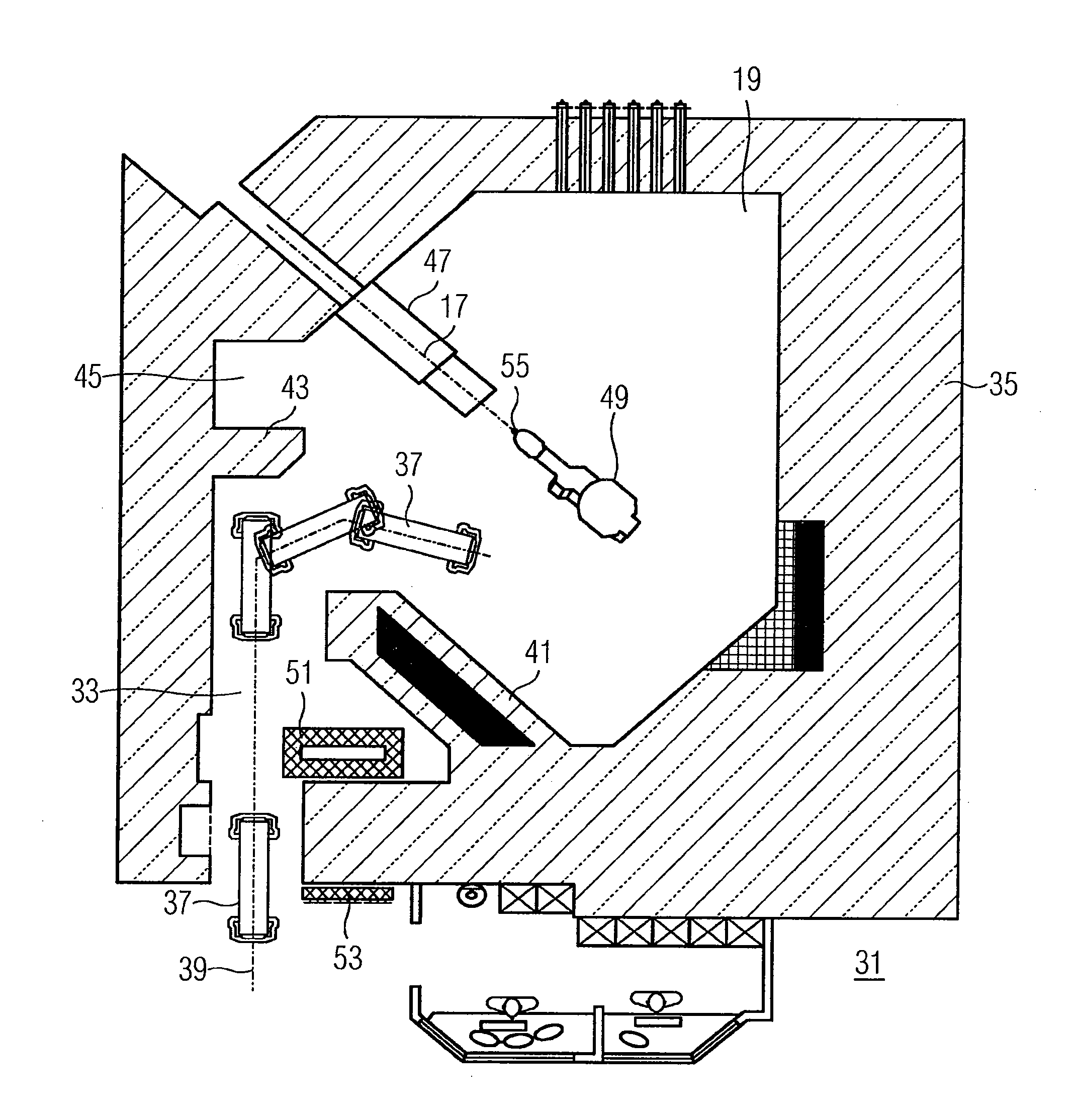
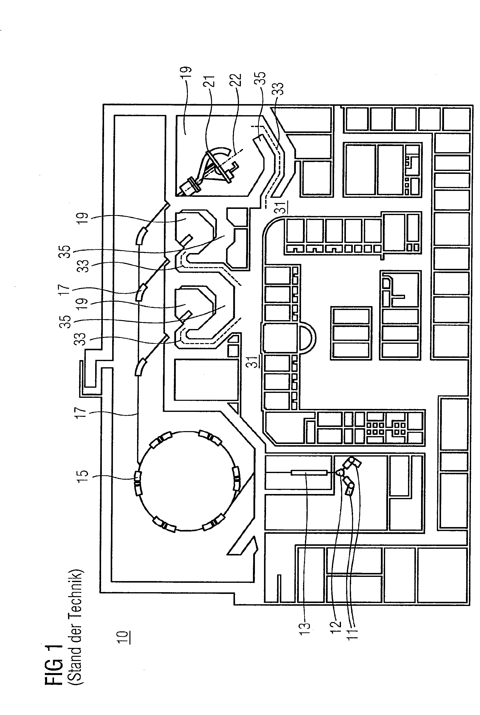
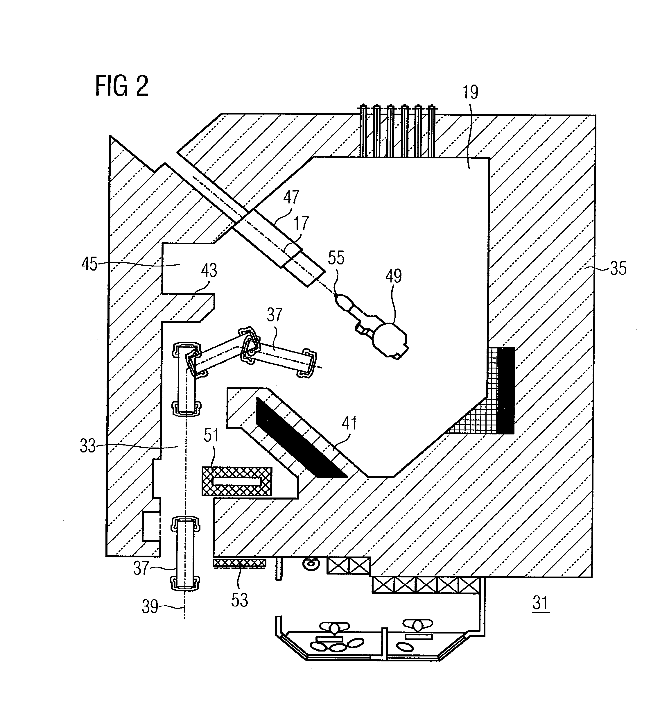
[0030]FIG. 1 shows a schematic view of the structure of a particle therapy system 10, as is known from the prior art. In the particle therapy system 10, a body (e.g., tumorous tissue in the body) is irradiated with a particle beam.

[0031]Ions such as, for example, protons, pions, helium ions, carbon ions or other sorts of ions, are used as particles. The particles are created in a particle source 11. If, as shown in FIG. 1, two particle sources 11, which generate two different types of ions, are provided, a switchover may be made within a very short time between the two different types of ions. A switching magnet 12, which is arranged between the ion source 11 and a pre-accelerator 13, may be used for the switchover. This allows the particle therapy system 10 to be operated with protons and with carbon ions at the same time, for example.

[0032]The particles generated by the particle source 11, or by one of the particle sources 11 and selected by the switching magnet 12 are accelerated...


PUM


Abstract

A particle therapy system that includes at least one irradiation chamber, in which an object is irradiated with a treatment beam, an antechamber, which is screened off from radiation occurring in the irradiation chamber and from which access is made to the irradiation chamber, and an access area, which leads to the irradiation chamber and connects the irradiation chamber to the antechamber, is provided. A support for a patient moves along a path of travel from the antechamber, through the access area, to the irradiation chamber. A radiation protection door is arranged in the access area, and the access area is configured geometrically in such a way that the path of travel in the access area is substantially rectilinear.

Description

[0001]The present patent document is a §371 nationalization of PCT Application Serial Number PCT / EP2008 / 060369, filed on Aug. 7, 2008, designating the United States, which is hereby incorporated by reference. This patent document also claims the benefit of DE 10 2007 042 336.7, filed Sep. 6, 2007, which is also hereby incorporated by reference.BACKGROUND[0002]The present embodiments relate to a particle therapy system.[0003]In particle therapy, a particle beam including protons or heavy ions (e.g., carbon ions) is created with a suitable accelerator. The particle beam is guided in a radiation channel and exits via an exit window of the radiation channel into an irradiation chamber where the irradiation of a patient is undertaken. Depending on the design of the irradiation chamber, this can be done via a fixed beam exit window (e.g., fixed beam irradiation chambers) but also via a rotatable gantry to allow radiation from a number of angles.[0004]The costs involved in generating and s...

Claims


Application Information

Patent Timeline
Patent Type & Authority Applications(United States)
IPC IPC(8): G21F7/005A61N5/10
CPCA61N5/10A61N5/1079A61N2005/1087G21Y2004/30G21F7/005G21Y2002/304G21Y2002/401A61N2005/1094
Inventor GUNEYSEL, MURAT
Owner SIEMENS HEALTHCARE GMBH
Learn More