
Power Headroom Reporting Method

a power control and headroom technology, applied in power management, radio transmission, electrical equipment, etc., can solve the problems of power control commands being misinterpreted at the mobile terminal, such errors accumulate, etc., and achieve the effect of minimizing signalling overhead and optimizing uplink performan

Active Publication Date: 2010-07-08
NOKIA TECHNOLOGLES OY
View PDF15 Cites 31 Cited by
  • Summary
  • Abstract
  • Description
  • Claims
  • Application Information

AI Technical Summary

Benefits of technology

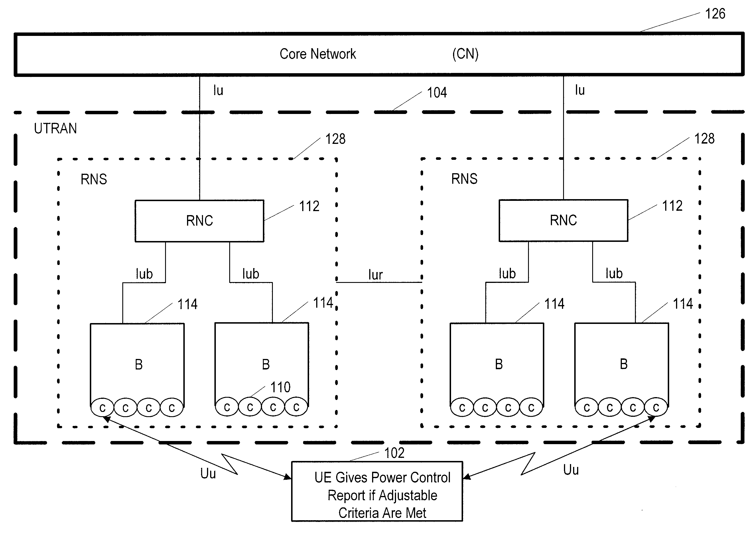
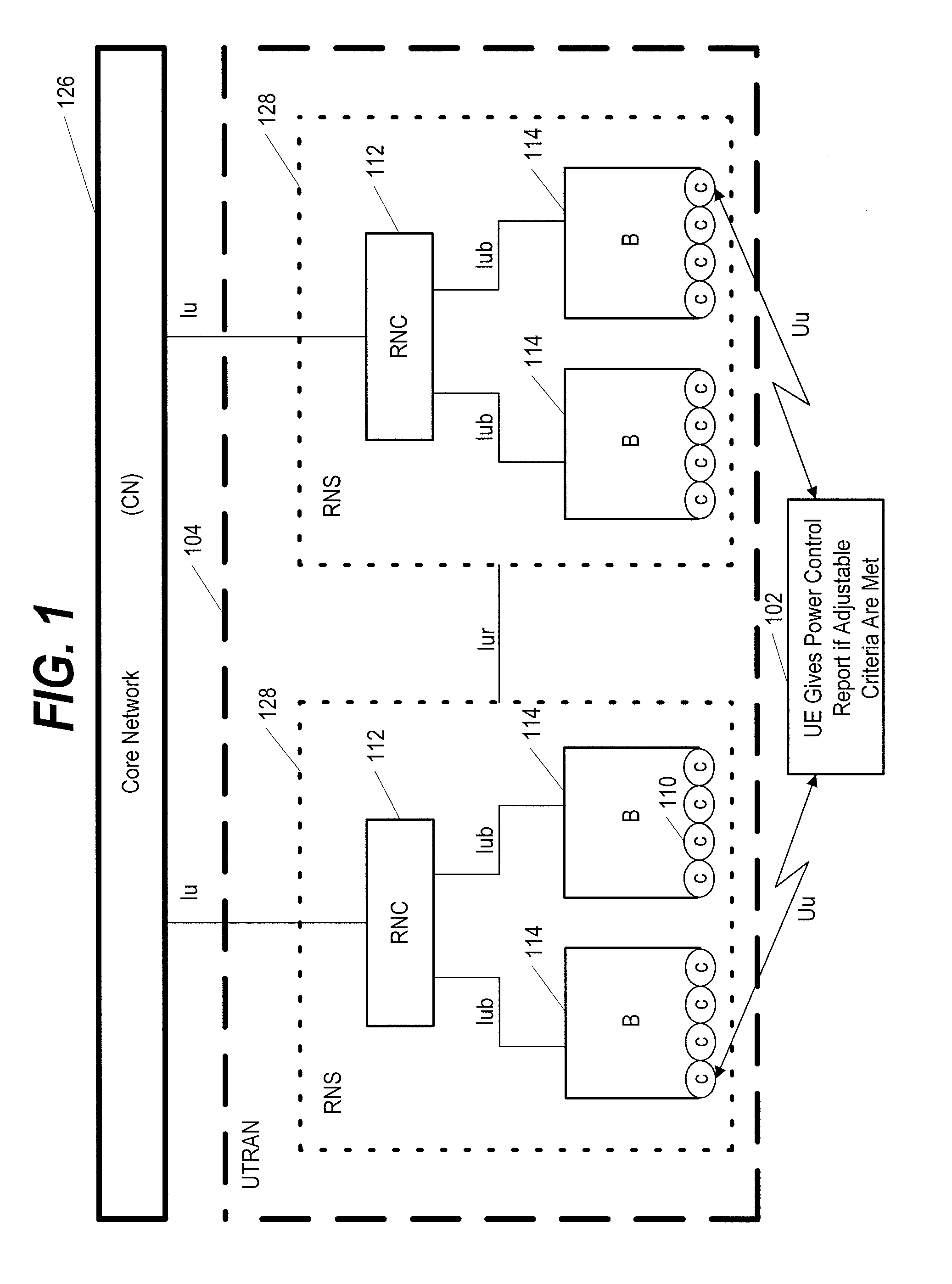
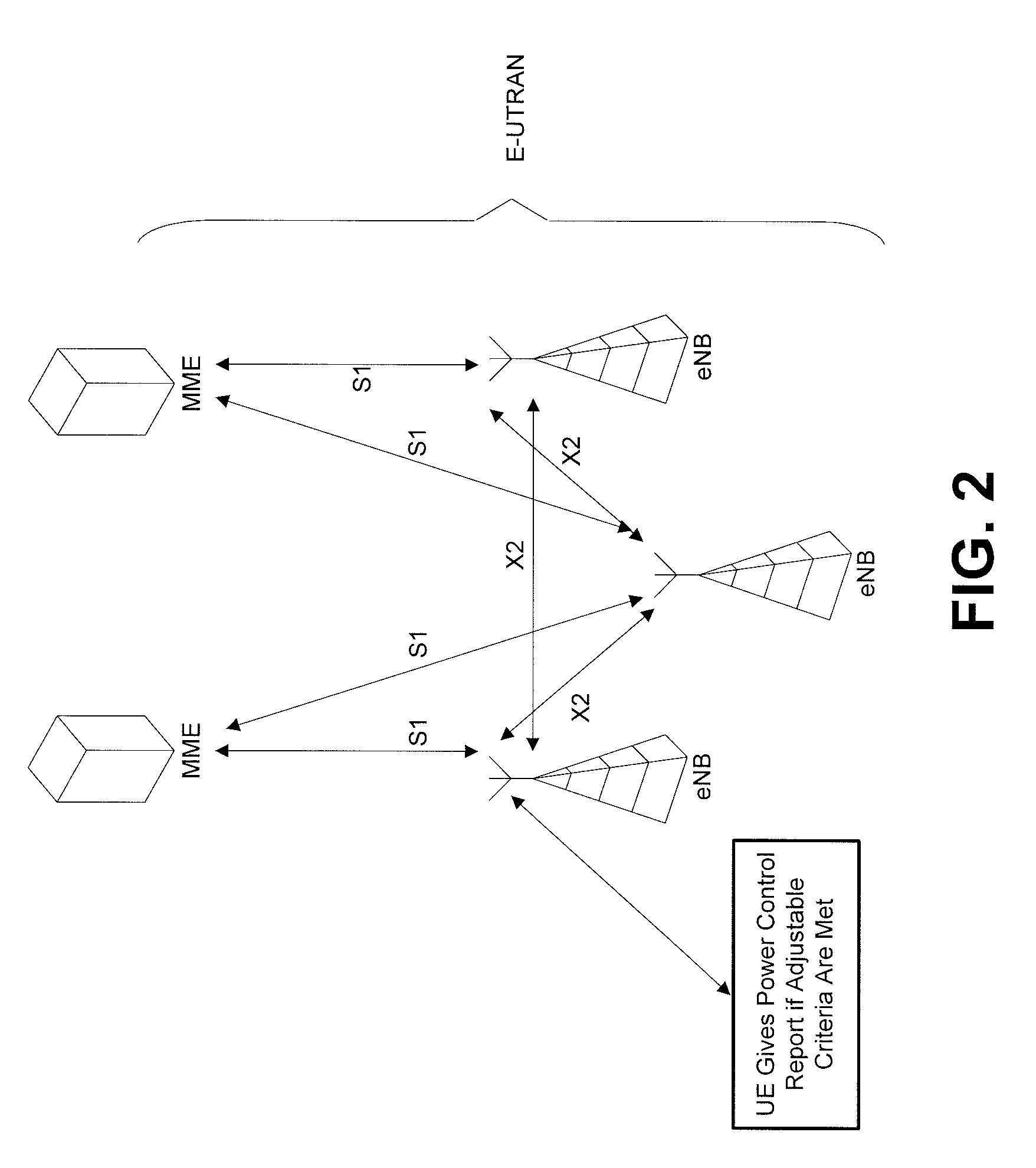
[0021]Although the present invention is applicable in the context of the E-UTRAN (LTE or 3.9G), its principles are not limited to such an environment, and instead may also be applicable to various other current and future wireless telecommunications systems and access technologies. This invention provides specific reporting criteria that are an attractive trade-off between signalling overhead versus overall uplink performance for LTE. The following triggering criteria are found to be very efficient for sending a power control headroom report in the uplink, while optimizing uplink performance, and while minimizing signalling overhead.

Problems solved by technology

The reason for this first criterion is, as already mentioned above, that the closed loop commands can be misinterpreted at the terminal and therefore tracking of power status at the eNodeB would lead to the accumulation of such errors.
The problem with power control commands being misinterpreted at the mobile terminal is only an issue if relative closed loop power control commands are used (which is also the working assumption in 3GPP).

Method used


Image

  • Power Headroom Reporting Method
  • Power Headroom Reporting Method
  • Power Headroom Reporting Method

Examples


Embodiment Construction

[0031]A preferred embodiment of the present invention will now be described. This is merely to illustrate one way of implementing the invention, without limiting the scope or coverage of what is described elsewhere in this application.

[0032]In this preferred embodiment, the reporting criteria are implemented in the terminal. However, the protocol for signalling the parameters “n”, “m”, “k” and / or “p” requires implementation at both the eNode-B and the terminal. This embodiment of the invention provides an attractive trade-off between signalling overhead and performance.

[0033]As seen in FIG. 3, the method 300 can begin with the base station adjusting 307 one or more of the thresholds “n”, “m”, “k” and / or “p” at the user equipment (UE) by signalling to the UE. At some subsequent point in time, the UE determines 315 that a triggering criterion has been met because one of those thresholds have been reached (or some combination of those thresholds have been reached). This will trigger th...


PUM


Abstract

A method, user equipment, network device, and software product enable a user equipment to determine that at least one of several triggering criterion have been met, in which case the user equipment provides a power control headroom report on an uplink from the user equipment. The triggering criterion includes a threshold having been reached, and the threshold is adjustable via a signal to the user equipment from a base station (such as an eNodeB).

Description

FIELD OF THE INVENTION[0001]The invention relates to the field of wireless telecommunications. More particularly, the present invention pertains to power control.BACKGROUND OF THE INVENTION[0002]The telecommunications industry is in the process of developing a new generation of flexible and affordable communications that includes high-speed access while also supporting broadband services. Many features of the third generation (3G) mobile telecommunications system have already been established, but many other features have yet to be perfected. The Third Generation Partnership Project (3GPP) has been pivotal in these developments.[0003]One of the systems within the third generation of mobile communications is the Universal Mobile Telecommunications System (UMTS) which delivers voice, data, multimedia, and wideband information to stationary as well as mobile customers. UMTS is designed to accommodate increased system capacity and data capability. Efficient use of the electromagnetic sp...

Claims


Application Information

Patent Timeline
Patent Type & Authority Applications(United States)
IPC IPC(8): H04W52/04
CPCH04W52/146H04W52/365
Inventor MICHEL, JUERGENPEDERSEN, KLAUS INGEMANNROSA, CLAUDIO
Owner NOKIA TECHNOLOGLES OY
Learn More