Catheter and tunneling device therefor

a tunneling device and catheter technology, applied in the field of catheters, can solve the problems of catheter uselessness, loss of catheter function, and clogged lumen, and achieve the effects of reducing long term infections, preventing clogging of lumens, and improving long term health benefits

Active Publication Date: 2010-07-08
ATKINS JOSEPH R
View PDF32 Cites 3 Cited by
  • Summary
  • Abstract
  • Description
  • Claims
  • Application Information

AI Technical Summary

Benefits of technology

[0011]Yet another feature of the invention is to provide a catheter inlet which is substantially less prone to be blocked off as a result of sucking up against the blood vessel wall.
[0012]A further feature of the invention is to provide a catheter that has the ability to substantially prevent clotting of the lumens of the catheter without the need of clot busting agents.
[0013]Another feature of the invention is to provide a catheter with the ability to reduce long term infections that accompany long term placement of central venous lines.
[0014]A further feature of the invention is to improve long term health benefits for hemodialysis and plasmaphoresis patients with improved blood flow rates.
[0015]Yet another feature of the invention is to provide a catheter that can safely access the blood circulatory system of humans and animals with minimal risk of air embolism.
[0020]In addition, the present invention provides for a tunneling device for use in inserting the catheter. In one embodiment, the tunneling device includes a relatively rigid member having a handle and an end which is of a length longer than the first end of catheter and is configured with an exposed elongated channel to receive the first end of the catheter. The tunneling device end is equipped with a hollow cap to receive the openings of the first end of the catheter in a manner to maintain the openings substantially covered during insertion of the catheter into the body thereby preventing potential clogging thereof by tissue and blood. The channel can be generally oval shaped to contain the connected conduit parts of the catheter. Further, the tunneling device can include a mid-section having a Y-shaped exposed channel continuous with the exposed elongated channel to receive at least part of the Y-shaped joint of the catheter.

Problems solved by technology

A problem in many dialysis catheters is clotting and fibrin sheath formation around the “arterial” inlet used for aspiration of blood from a patient.
Thrombus and fibrin can occlude distal tips or other places throughout the length of the catheter lumens, resulting in loss of catheter function when such an occlusion prevents blood flow.
Unfortunately, the small holes become filled with fibrin and the large inlet hole develops a trap door clot, which makes the catheter useless.
A secondary problem is that related to the arterial lumen “sucking” against the vessel wall in which it resides.
This problem can occur if the arterial lumen ports become fully occluded by the patient's vasculature.
This causes cleaned blood to flow directly toward the lumen that is under vacuum, line reversal in certain catheters can result in inefficient flow and (high re-circulation).
Additionally, there are major side effects which carry patient safety issues, such as hemorrhaging due to the use of indwelling anticoagulants.
Another major issue is that of infection.
This cuff design is often inadequate to perform these functions.

Method used


Image

  • Catheter and tunneling device therefor
  • Catheter and tunneling device therefor
  • Catheter and tunneling device therefor

Examples


Embodiment Construction

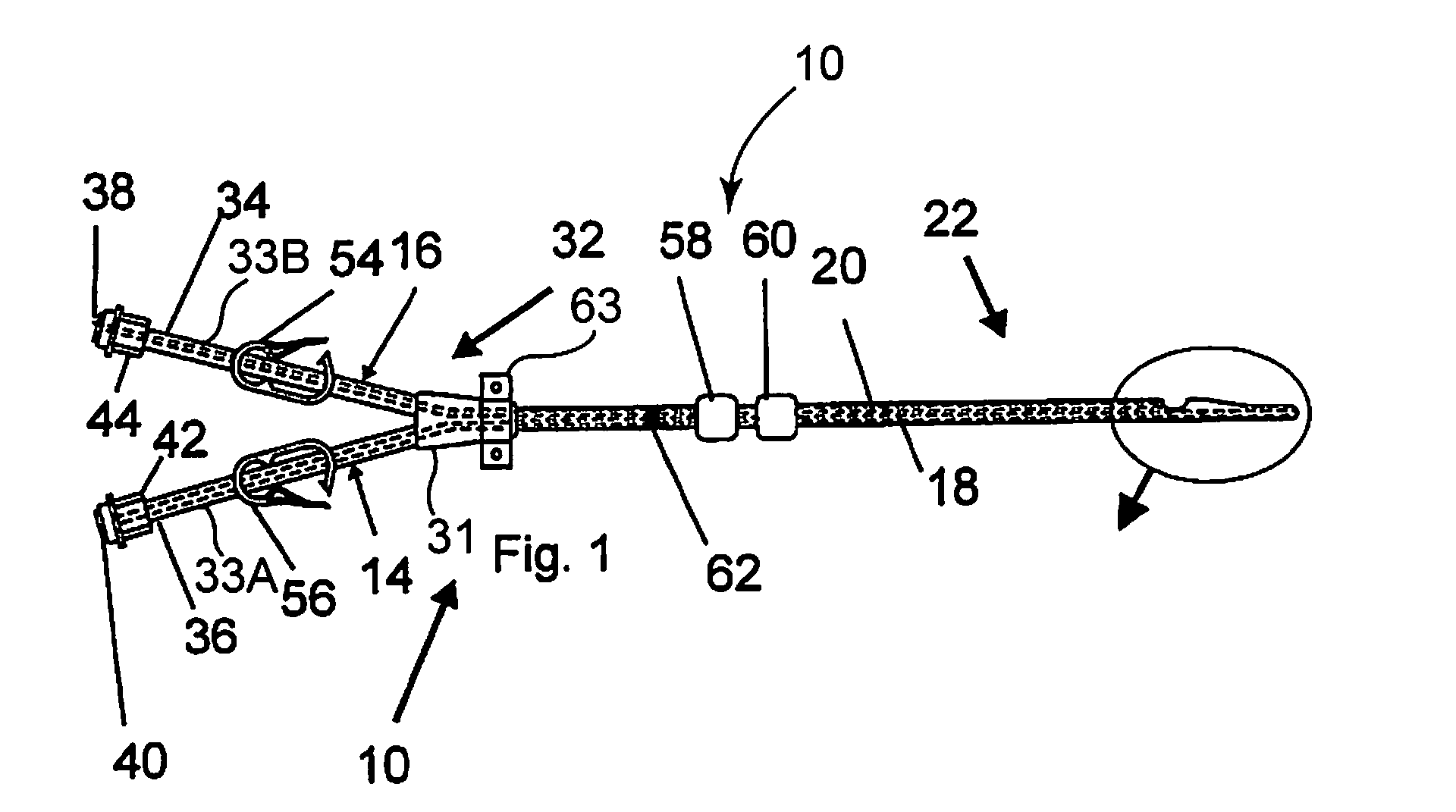
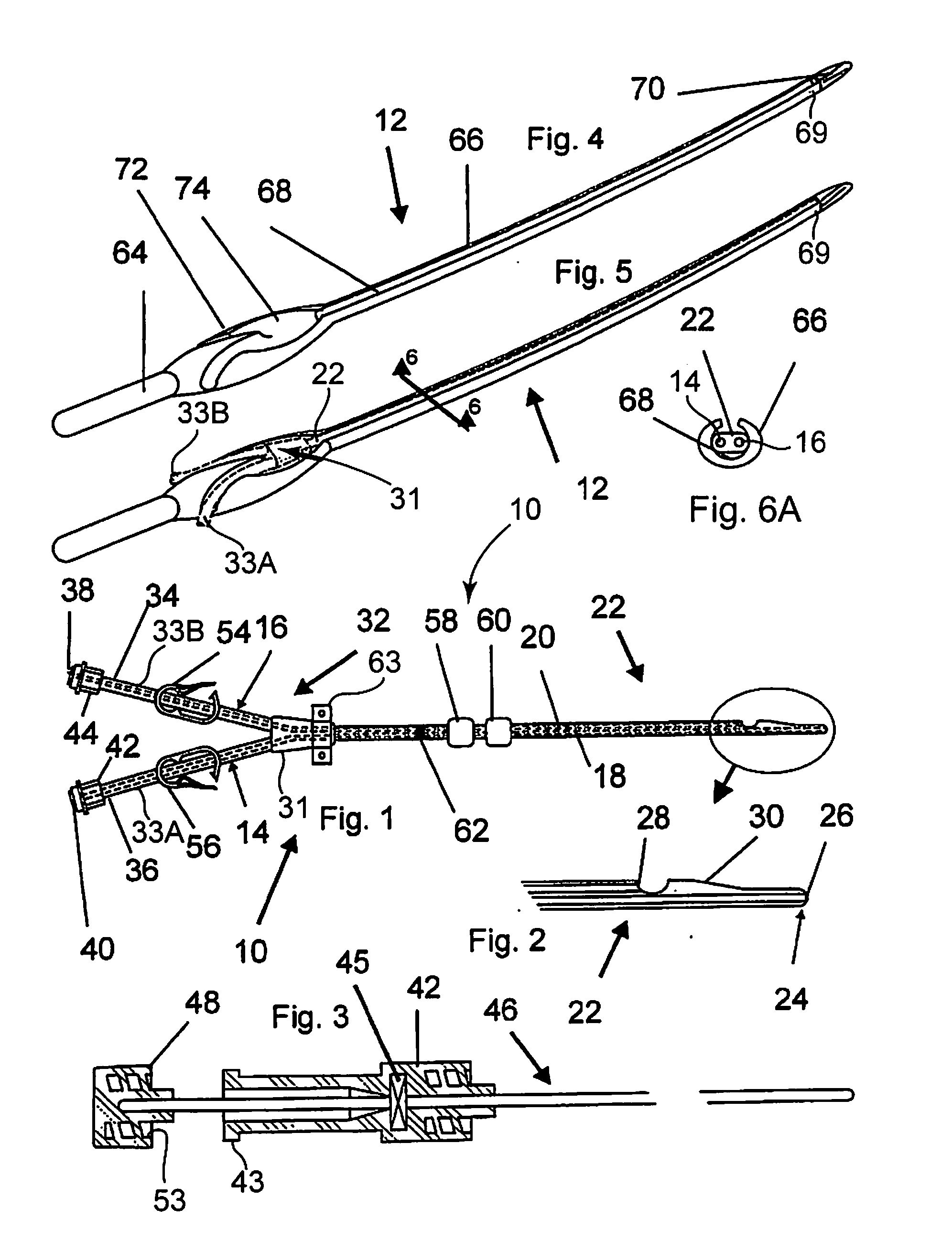
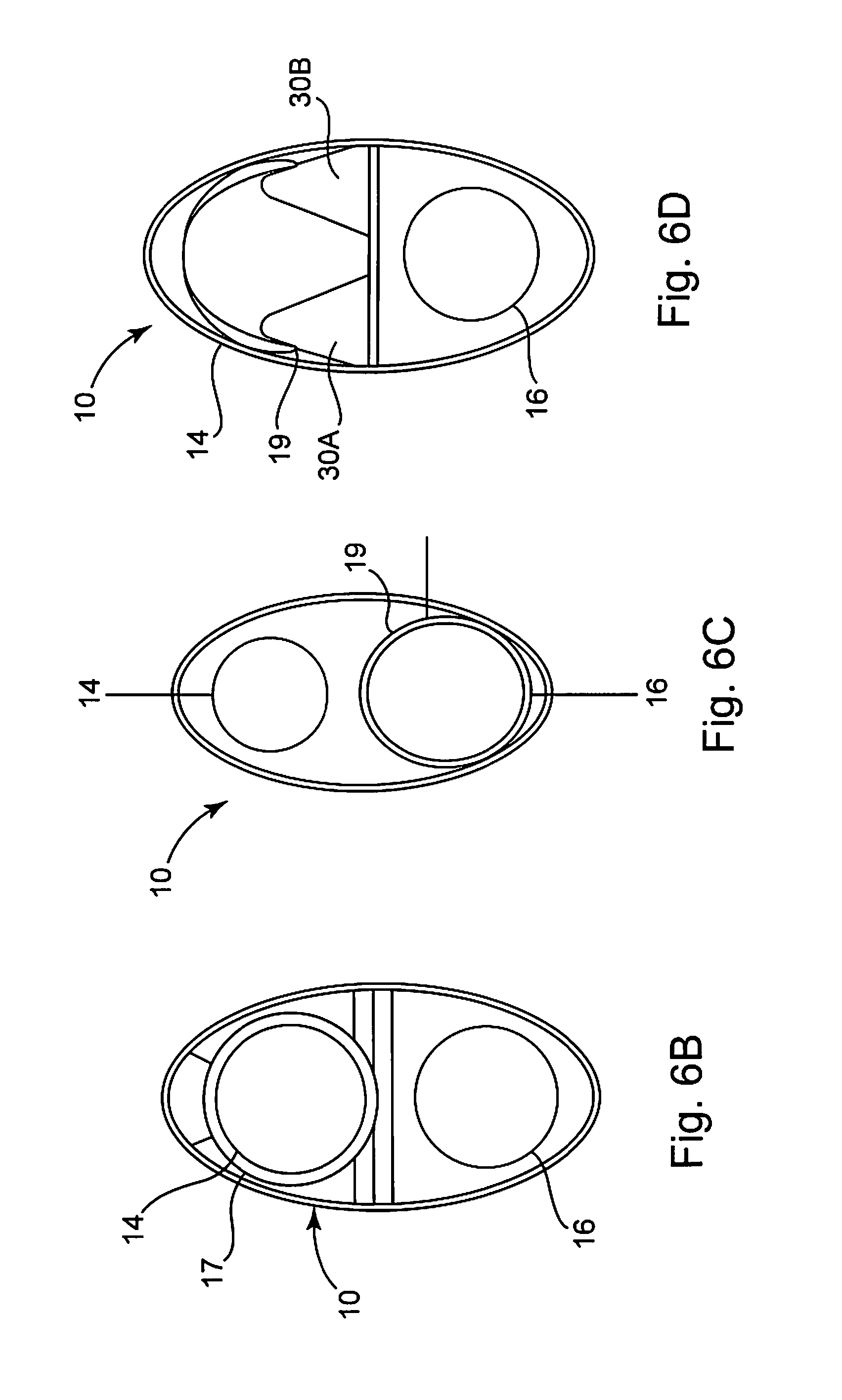
[0035]Referring now to the drawings, the present invention in one exemplary embodiment is generally directed to a catheter 10 for introduction and removal of fluids from a body B and a tunneling device 12 to more readily enable insertion of the catheter 10. The catheter 10 includes a first lumen 14 for removing fluid from the body B and another lumen 16 for delivering fluid to the body. The lumens 14 and 16 include distal lumen segments 18, 20, respectively, which are integrally connected as part of a first end 22 of the catheter 10 and extend along side one another. Preferably, the catheter 10 is made of a biologically inert, somewhat flexible, material, such as, but not limited to, a urethane or polyurethane-based material, such as CARBOTHANE® (available from Thermedics Corp.), polyether block amides, such as PEBAX® (available from Arkema Inc.) or other material known to those skilled in the art that possesses sufficient bioinertness, durability, flexibility and moldability or ext...


PUM


Abstract

A catheter for introduction and removal of fluids from a body and tunneling device therefor, the catheter has a body having a first conduit for removing fluid from the body and a second conduit for delivering fluid to the body wherein at least a part of each of the lumens is integrally formed within a first end of the body and extends along side one another. The first conduit extends beyond the second conduit and forms a terminal point of the first end and defines a first opening thereat and the second conduit extends to a point short of the terminal point defining a second opening. A bumper portion is adjacent the second opening extending toward the terminal point. Another part of each the first and the second lumens are disjoined and form part of a second Y-shaped end. The tunneling device has a channel to removably receive the catheter.

Description

CROSS-REFERENCE TO RELATED APPLICATIONS[0001]This application is a continuation-in-part of copending application Ser. No. 11 / 161,212, filed Jul. 27, 2005, entitled CATHETER AND TUNNELING DEVICE THEREFOR, and No. 29 / 244,662, filed Dec. 13, 2005, entitled TUNNELING DEVICE FOR A CATHETER, both commonly assigned to the assignee of the present application, the disclosures of which are incorporated by reference in their entirety herein.FIELD OF INVENTION[0002]The present invention relates to catheters and more particularly to an improved catheter for introduction and removal of fluids from a body and to a tunneling device to more readily enable insertion of the catheter.BACKGROUND OF THE INVENTION[0003]Medical catheters have been used successfully for many years to access the blood stream of human and animal patients. Multi-lumen catheters are used for a variety of applications where it is necessary to have two or more separate fluid pathways. The purposes of accessing the blood circulato...

Claims


Application Information

Patent Timeline
Patent Type & Authority Applications(United States)
IPC IPC(8): A61M25/14A61M25/01
CPCA61M25/0028A61M25/0029A61M25/0068A61M1/3661A61M25/0662A61M2025/0031A61M2025/0037A61M25/0194
Inventor ATKINS, JOSEPH R.CATLIN, DAVID GEORGE
Owner ATKINS JOSEPH R
Why Eureka
Try Eureka