Catheter and tunneling device therefor

a tunneling device and catheter technology, applied in the field of catheters, can solve the problems of loss of catheter function, inefficient flow, inconvenient use of catheters, etc., and achieve the effects of reducing long-term infections, preventing clotting of lumens, and improving long-term health benefits

Inactive Publication Date: 2009-09-03
ATKINS JOSEPH R
View PDF17 Cites 7 Cited by
  • Summary
  • Abstract
  • Description
  • Claims
  • Application Information

AI Technical Summary

Benefits of technology

[0010]Yet another object of the invention is to provide a catheter inlet which is substantially less prone to be blocked off as a result of sucking up against the blood vessel wall.
[0011]A further object of the invention is to provide a catheter that has the ability to substantially prevent clotting of the lumens of the catheter without the need of clot busting agents.
[0012]Another object of the invention is to provide a catheter with the ability to reduce long term infections that accompany long term placement of central venous lines.
[0013]A further object of the invention is to improve long term health benefits for hemodialysis and plasmaphoresus patients with improved blood flow rates.
[0014]Yet another object of the invention is to provide a catheter that can safely access the blood circulatory system of humans and animals with minimal risk of air embolism.
[0019]In addition, the present invention provides for a tunneling device for use in inserting the catheter. The tunneling device includes a relatively rigid member having a handle and an end which is of a length longer than the first end of catheter and is configured with an exposed elongated channel to receive the first end of the catheter. The tunneling device end is equipped with a hollow cap to receive the openings of the first end of the catheter in a manner to maintain the openings substantially covered during insertion of the catheter into the body thereby preventing potential clogging thereof by tissue and blood. The channel can be generally oval shaped to contain the connected conduit parts of the catheter. Further, the tunneling device can include a mid section having a Y-shaped exposed channel continuous with the exposed elongated channel to receive at least part of the Y-shaped end of the catheter.

Problems solved by technology

A problem in many dialysis catheters is that related to clotting and fibrin sheath formation around the “arterial” inlet used for aspiration of blood from a patient.
Thrombus and fibrin can occlude distal tips or other places throughout the length of the catheter lumens, resulting in loss of catheter function when such an occlusion prevents blood flow.
Unfortunately, the small holes become filled with fibrin and the large inlet hole develops a trap door clot, which makes the catheter useless.
A secondary problem is that related to the arterial lumen “sucking” against the vessel wall in which it resides.
This problem can occur if the arterial lumen ports become fully occluded by the patient's vasculature.
This causes cleaned blood to flow directly toward the lumen that is under vacuum, line reversal in certain catheters can result in inefficient flow and (high re-circulation).
Additionally, there are major side effects which carry patient safety issues, such as hemorrhaging due to the use of indwelling anticoagulants.
Another major issue is that of infection.
This cuff design is often inadequate to perform these functions.

Method used


Image

  • Catheter and tunneling device therefor
  • Catheter and tunneling device therefor
  • Catheter and tunneling device therefor

Examples


Embodiment Construction

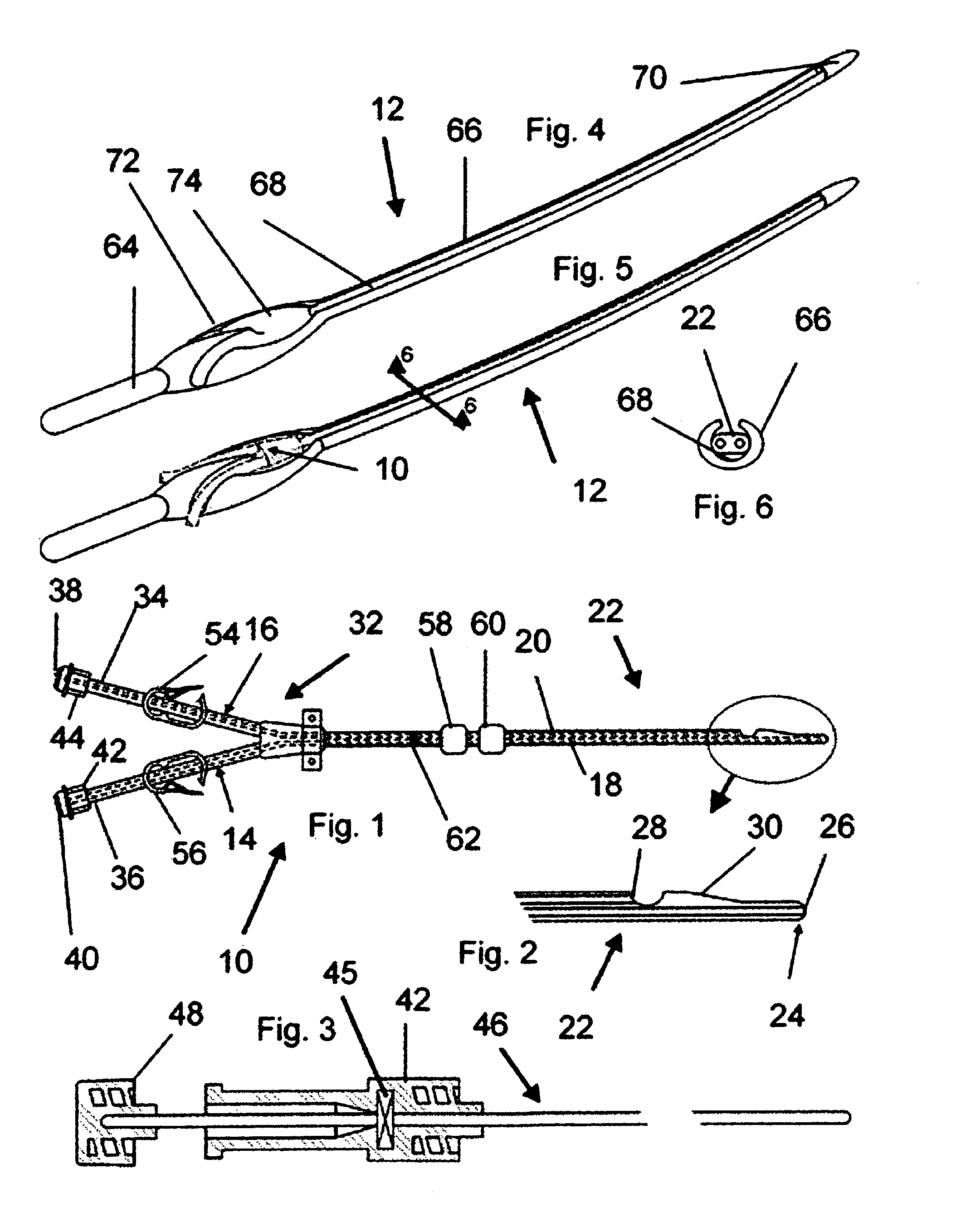
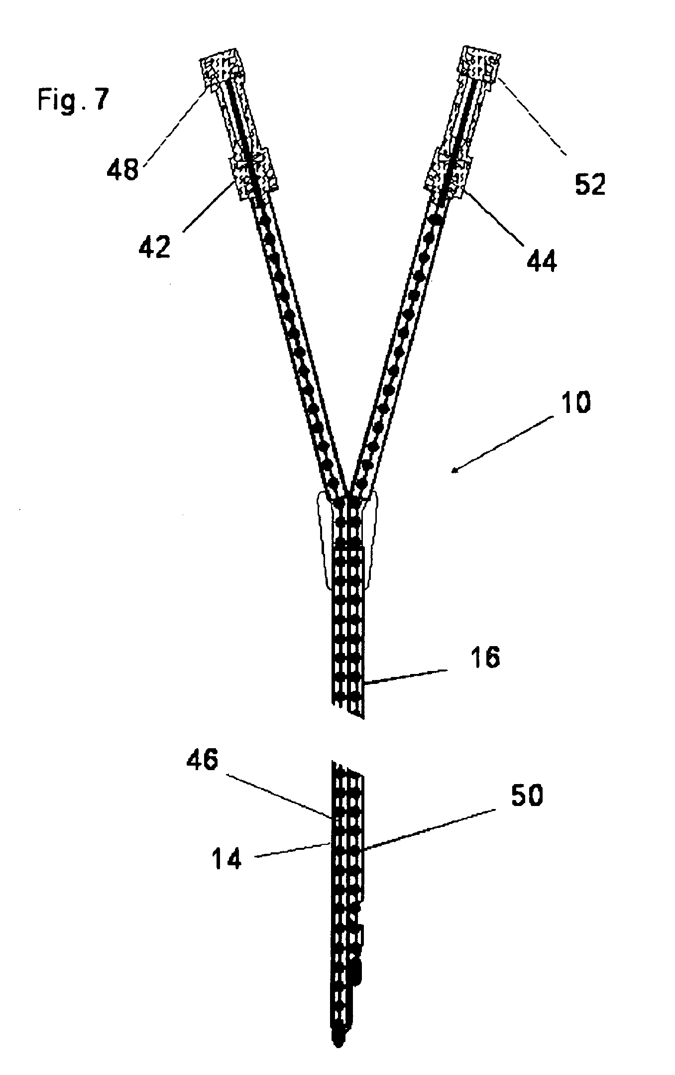
[0030]Referring now to the drawings, the present invention is generally directed to a catheter 10 for introduction and removal of fluids from a body B and a tunneling device 12 to more readily enable insertion of the catheter 10. The catheter 10 includes a first conduit 14 for removing fluid from the body B and another conduit 16 for delivering fluid to the body. Parts 18 and 20 of each of the conduits 14 and 16, respectively, are integrally connected as part a first end 22 of the catheter 10 and. extend along side one another.

[0031]The first conduit 14 can preferably be the fluid delivering conduit (venous flow) which extends beyond the second conduit 16 as best seen in FIGS. 1 and 2 and forms a terminal point 24 of the first end 22 and defines a first opening 26 thereat. The second conduit 16 can preferably be the fluid receiving conduit (arterial flow) which extends to a point short of the terminal point 24 and defines a second opening 28. Also, a bumper portion 30, which can pre...


PUM


Abstract

A catheter for introduction and removal of fluids from a body and tunneling device therefor, the catheter has a body having a first conduit for removing fluid from the body and a second conduit for delivering fluid to the body wherein at least a part of each of the conduits is integrally formed within a first end of the body and extends along side one another. The first conduit extends beyond the second conduit and forms a terminal point of the first end and defines a first opening thereat and the second conduit extends to a point short of the terminal point defining a second opening. A bumper portion is adjacent the second opening extending toward the terminal point. Another part of each the first and the second conduits are disjoined and form part of a second Y-shaped end. The tunneling device has a channel to removably receive the catheter.

Description

FIELD OF INVENTION[0001]The present invention relates to catheters and more particularly to an improved catheter for introduction and removal of fluids from a body and a tunneling device to more readily enable insertion of the catheter.BACKGROUND OF THE INVENTION[0002]Medical catheters have been used successfully for many years to access the blood stream of human and animal patients. Multi-lumen catheters are used for a variety of applications where it is necessary to have two or more separate fluid pathways. The purposes of accessing the blood circulatory system include introduction of medication, hemodialysis therapy, plasmaphoresis therapy, and other therapies which may require access to the blood circulatory system.[0003]In the case of hemodialysis, a dual-lumen catheter can be employed to simultaneously accommodate opposing blood flow. One lumen aspirates blood from a blood vessel of a patient to a dialysis machine where it is processed for the removal of toxins, while the othe...

Claims


Application Information

Patent Timeline
Patent Type & Authority Applications(United States)
IPC IPC(8): A61M1/14A61M25/06
CPCA61M25/0029A61M25/0068A61M1/3659A61M2025/0031A61M2025/0037A61M25/0194
Inventor ATKINS, JOSEPH R.
Owner ATKINS JOSEPH R
Why Eureka
Try Eureka