Thermally efficient window assembly

a window assembly and thermal efficiency technology, applied in the direction of door/window protective devices, wing accessories, wing arrangements, etc., can solve the problems of reducing the thermal efficiency of the window assembly, and achieve the effect of increasing the thickness of the interior surface and increasing the thermal performance of the window assembly

Inactive Publication Date: 2010-07-15
YKK AP AMERICA INC
View PDF25 Cites 20 Cited by
  • Summary
  • Abstract
  • Description
  • Claims
  • Application Information

AI Technical Summary

Benefits of technology

[0010]For example, in a particular embodiment, the thickness of the interior surface of the frame is about 35% greater than the thickness of the exterior surface of the frame. By increasing the thickness of the interior surface, the interior surface acts as a heat sink during cooler months—storing radiant heat received through the glass panel and any heat transferred to the interior surface through conduction or convection from the exterior surface. Because the convection currents in the interior area of the building can be significantly larger than the convection currents that may form in the chamber(s) between the interior surface and the exterior surface, less of the heat stored in the interior surface is released to the exterior area of the building. According to one embodiment, this arrangement increases the thermal performance of the window assembly during the cooler months.

Problems solved by technology

These convection currents transfer heat from the warmer portions of the sash and frame to the cooler portions of the sash and frame, which can reduce the thermal efficiency of the window assembly.

Method used


Image

  • Thermally efficient window assembly
  • Thermally efficient window assembly
  • Thermally efficient window assembly

Examples


Embodiment Construction

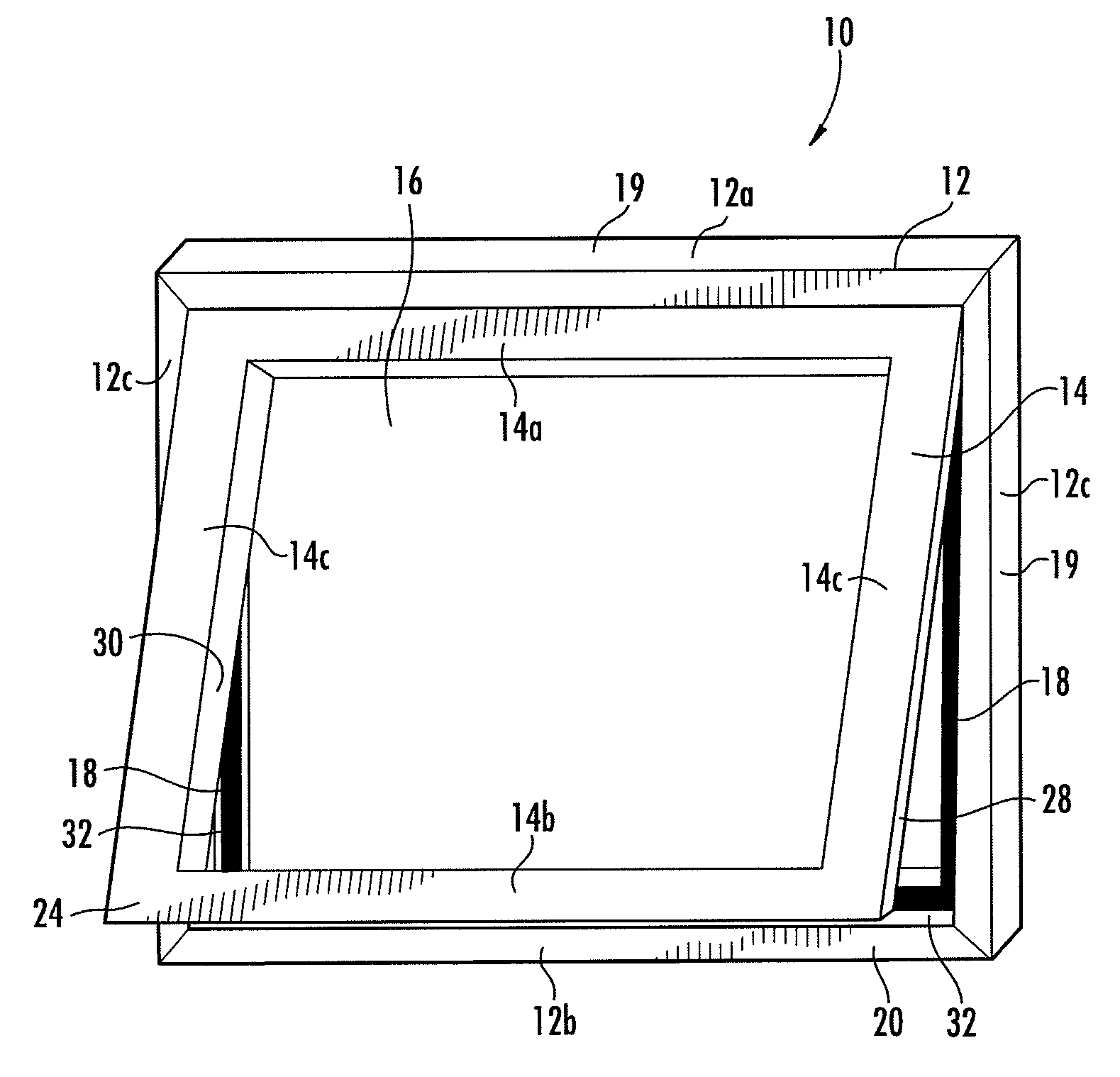
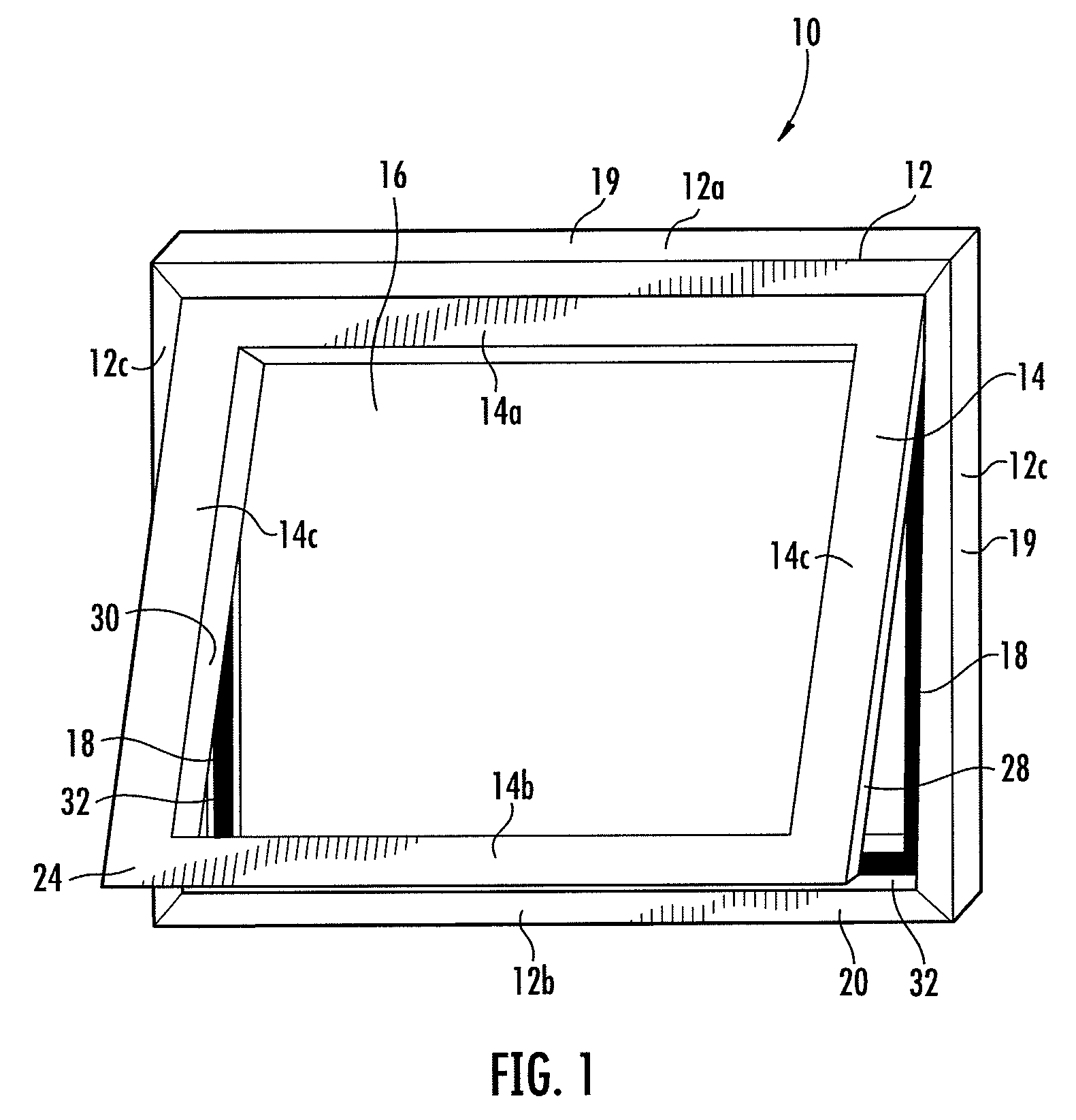
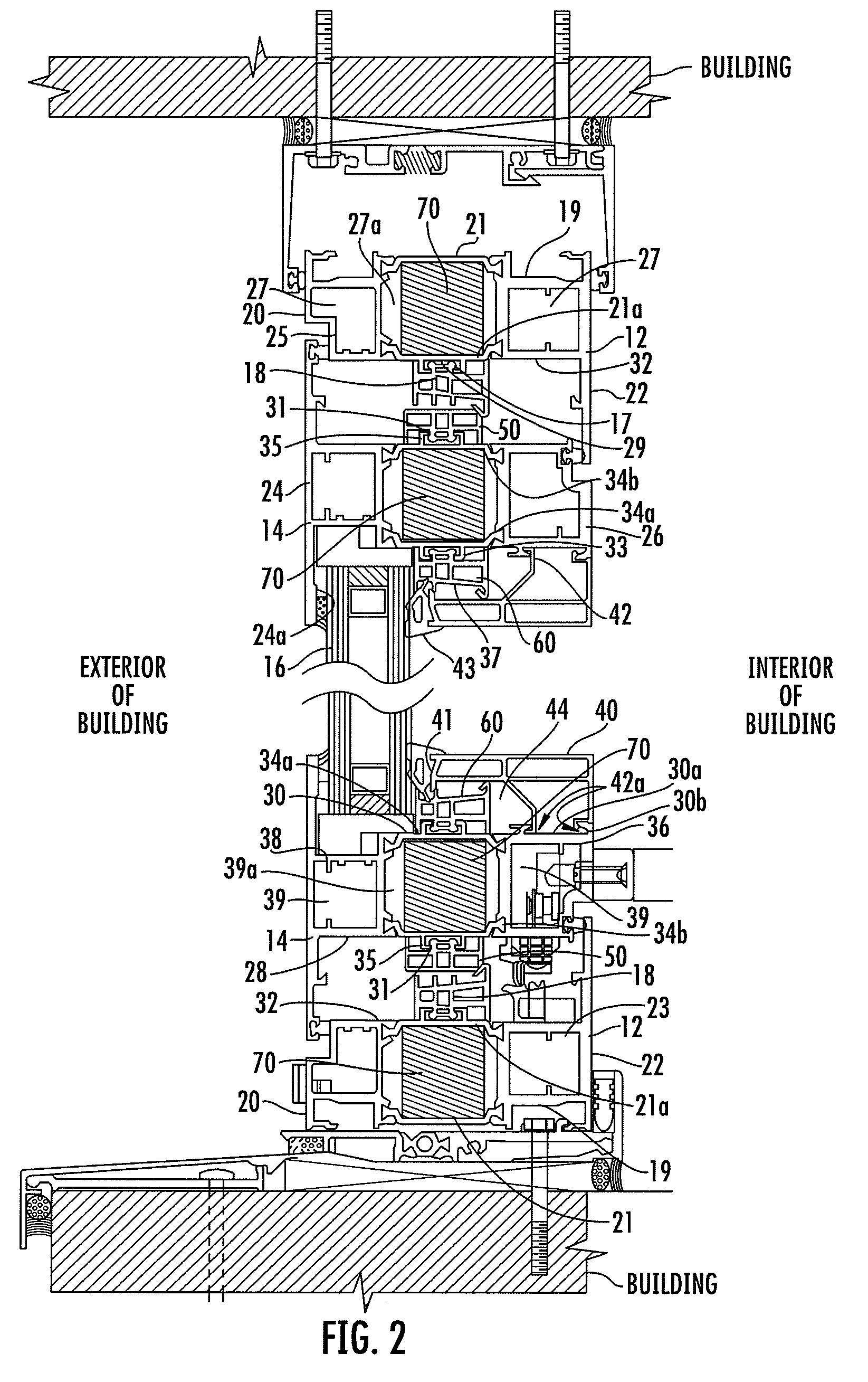
[0003]Various embodiments of an operable window assembly include a frame, a sash, and at least one elongated frame insulating element that is formed separately from the frame. The frame has an inner surface, and the inner surface defines a track that extends outwardly from the inner surface. The track defines a retaining channel along a longitudinal axis of the track. The sash has an outer surface, and the sash is mounted within the frame such that the outer surface of the sash is disposed opposite to and cofaces the inner surface of the frame. The at least one elongated frame insulating element includes a frame engaging protrusion that extends outwardly from a first surface of the at least one elongated frame insulating element, and the frame engaging protrusion is slidably disposed within the retaining channel. In addition, the at least one elongated frame insulating element defines a plurality of chambers that extend substantially parallel to a longitudinal axis of the at least o...


PUM


Abstract

A window assembly according to various embodiments includes a frame, a sash, an insulating unit (e.g., one or more glass panels), a glass stop, an elongated frame insulating element slidably disposed on an inner surface of the frame, an elongated sash insulating element slidably disposed on an outer surface of the sash, and an elongated inner sash insulating element slidably disposed on an inner surface of the sash. The elongated frame insulating element, the elongated sash insulating element, and the elongated inner sash insulating element each define a plurality of chambers that extend substantially parallel to a longitudinal axis of each element. These chambers reduce the size of the space between the frame and sash and the size of the space between the sash, the insulating unit, and the glass stop, which results in smaller convection currents within these spaces and a more thermally efficient window assembly.

Description

BACKGROUND OF THE INVENTION[0001]In general, an operable window assembly includes a sash, frame, and one or more glass panels (e.g., monolithic glass or insulating units having two or more glass panels). The one or more glass panels are mounted within the sash adjacent the inner surface of the sash, and the sash is mounted within the frame adjacent the inner surface of the frame. The frame is then mounted into an opening of a building such that the outer surface of the frame is adjacent a wall of the building that defines the opening. The sash and frame may include hollow chambers extending longitudinally within the sash and the frame, and heat differentials between the exterior surfaces of the sash and frame and the interior surfaces of the sash and frame generate convection currents of air between the sash and frame and within the hollow chambers. These convection currents transfer heat from the warmer portions of the sash and frame to the cooler portions of the sash and frame, wh...

Claims


Application Information

Patent Timeline
Patent Type & Authority Applications(United States)
IPC IPC(8): E06B3/00E06B3/34
CPCE06B7/10E06B2003/26389E06B2007/026E06B2003/6244E06B2003/6264E06B2003/6223
Inventor MORIYA, MASANORIUHL, JOHNITO, TSUTOMUBRAUNSTEIN, RICHARD
Owner YKK AP AMERICA INC
Why Eureka
Try Eureka