Low power consuming desorption apparatus and dehumidifier using the same

a dehumidifier and low power consumption technology, applied in the direction of chemistry apparatus and processes, separation processes, dispersed particle separation, etc., can solve the problems of high power consumption, high approach cost, and depletion of ozone layer, and achieve the effect of enhancing desorption rate and low power consumption

Inactive Publication Date: 2010-07-15
IND TECH RES INST
View PDF13 Cites 25 Cited by
  • Summary
  • Abstract
  • Description
  • Claims
  • Application Information

AI Technical Summary

Benefits of technology

[0007]The present invention provides a low power consumption desorption apparatus using electrodes disposed on both ends of an absorbing material so as to conduct an electric current flowing through the absorbing material to raise the temperature and desorb a substance absorbed by the absorbing material since the attractive force between the absorbed molecules and the absorbing material may change under some circumstances. Moreover, a regenerating gas path can be provided in a region corresponding to the electrodes so that the gas flow passes through the absorbing material to enhance the desorption rate.

Problems solved by technology

However, the use of refrigerant results in problems such as ozone layer depletion.
However, this approach costs high power consumption to achieve dehumidifying because it takes a long time for vaporization to generate high-temperature gas required during moisture desorption.
Accordingly, in the aforesaid two approaches, conventional desorption approaches by heating up the circulating gas flow or thermally radiating the water molecules to achieve desorption inevitably lead to high power consumption since the radiated heat is mostly absorbed by the absorbing material.
Moreover, the radiated heat increases the surface temperature of the absorbing material, which adversely affects the absorption of water molecules by the desiccative to reduce the dehumidifying performance.
Therefore, in a rotary dehumidifier, the power consumption is high and dehumidification efficiency is reduced.

Method used


Image

  • Low power consuming desorption apparatus and dehumidifier using the same
  • Low power consuming desorption apparatus and dehumidifier using the same
  • Low power consuming desorption apparatus and dehumidifier using the same

Examples


Embodiment Construction

[0023]The present invention can be exemplified but not limited by the preferred embodiments as described hereinafter.

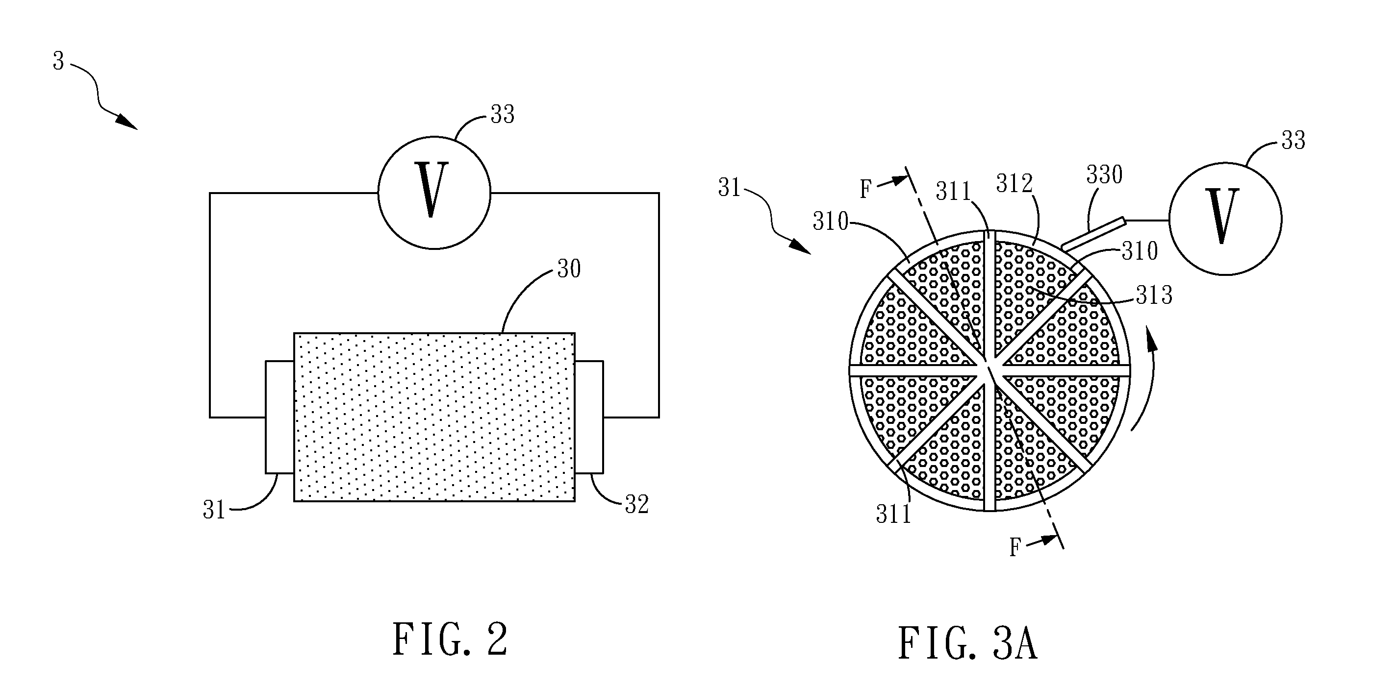
[0024]Please refer to FIG. 2, which is a schematic diagram of a low power consumption desorption apparatus according to one embodiment of the present invention. In the present embodiment, the desorption apparatus 3 comprises an absorbing material 30, a pair of electrodes 31 and 32 and a voltage supply 33. The absorbing material 30 is capable of absorbing volatile organic substances in the air, exemplified by, but not limited to, nitrogen or water moisture. Generally, the absorbing material is usually used in household dehumidifiers, such as rotary dehumidifier, but not limited thereto. The absorbing material can be made of porous materials such as zeolite, silicone, silica gel, active carbon, carbon nano tubes, metal organic frameworks. Moreover, the absorbing material may also be formed of non-porous materials such as dehydrogenated metal.

[0025]The pair of electrodes...


PUM


Abstract

The present invention provides a low power consumption desorption apparatus, which utilizes a pair of electrodes coupled to an absorbing material to provide an electric current flowing through the absorbing material so as to desorb the substances absorbed within the absorbing material. By means of the desorption apparatus of the present invention, the absorbing material is able to enhance the desorbing efficiency and reducing power consumption during desorption. The present invention further provides a dehumidifier using the low power consumption desorption apparatus for providing a continuous dry air flow to desorb and regenerate the moisture from the absorbing material so that the dehumidifier is capable of removing moisture in the air repeatedly to reduce the humidity.

Description

FIELD OF THE INVENTION[0001]The present invention generally relates to an environmental control technology and, more particularly, a low power consuming desorption apparatus and dehumidifier using the same wherein a voltage is applied across electrodes on both ends of a conductive material for desorption.BACKGROUND OF THE INVENTION[0002]Conventionally, the household dehumidifier uses a refrigerant compressor to condense the moisture in the air to achieve dehumidification. However, the use of refrigerant results in problems such as ozone layer depletion. Therefore, there is the need in developing a novel dehumidification technique without using refrigerant.[0003]In rotary desiccant dehumidification, the refrigerant compressor is not required; instead, an absorbing material is used to absorb the moisture in the air and then electrical-thermal heater is used to heat up the gas flow through a regenerating area of the absorbing material to desorb the moisture. The high-temperature and hi...

Claims


Application Information

Patent Timeline
Patent Type & Authority Applications(United States)
IPC IPC(8): B01D53/14
CPCB01D53/0438B01D2259/40096B01D53/261B01D53/06
Inventor SHIH, MING-SHIANNLIN, YU-LIHUANG, JAU-CHYNHUANG, TING-WEICHI, YEN-HSUNCHANG, YO-MINGJENG, MING-SHANCHOU, YA-WEN
Owner IND TECH RES INST
Why Eureka
Try Eureka