Braking device

a technology of braking device and nut, which is applied in the direction of braking system, rotary clutch, fluid coupling, etc., can solve the problems of weak force to press the nut to the retracting limit, inability to perform satisfactory regenerative control, and transmission of members, so as to reduce the time lag during the brake operation

Inactive Publication Date: 2010-07-15
ADVICS CO LTD
View PDF4 Cites 25 Cited by
  • Summary
  • Abstract
  • Description
  • Claims
  • Application Information

AI Technical Summary

Benefits of technology

[0022]In one preferable embodiment, the braking device of the present invention further includes a control unit configured to apply a current to the motor required for ca

Problems solved by technology

Therefore, in the case of a regenerative control or the like, when a torque of the motor is reduced, a force to press the nut to the retracting limit becomes weaker, and a problem may arise that the pushing force by the input transferring member is transmitted to the master piston.
In this case, a transmitting force to the master piston cannot be suppressed up to an equivalent level to the pushing force by the input transferring member,

Method used


Image

  • Braking device
  • Braking device
  • Braking device

Examples


first embodiment

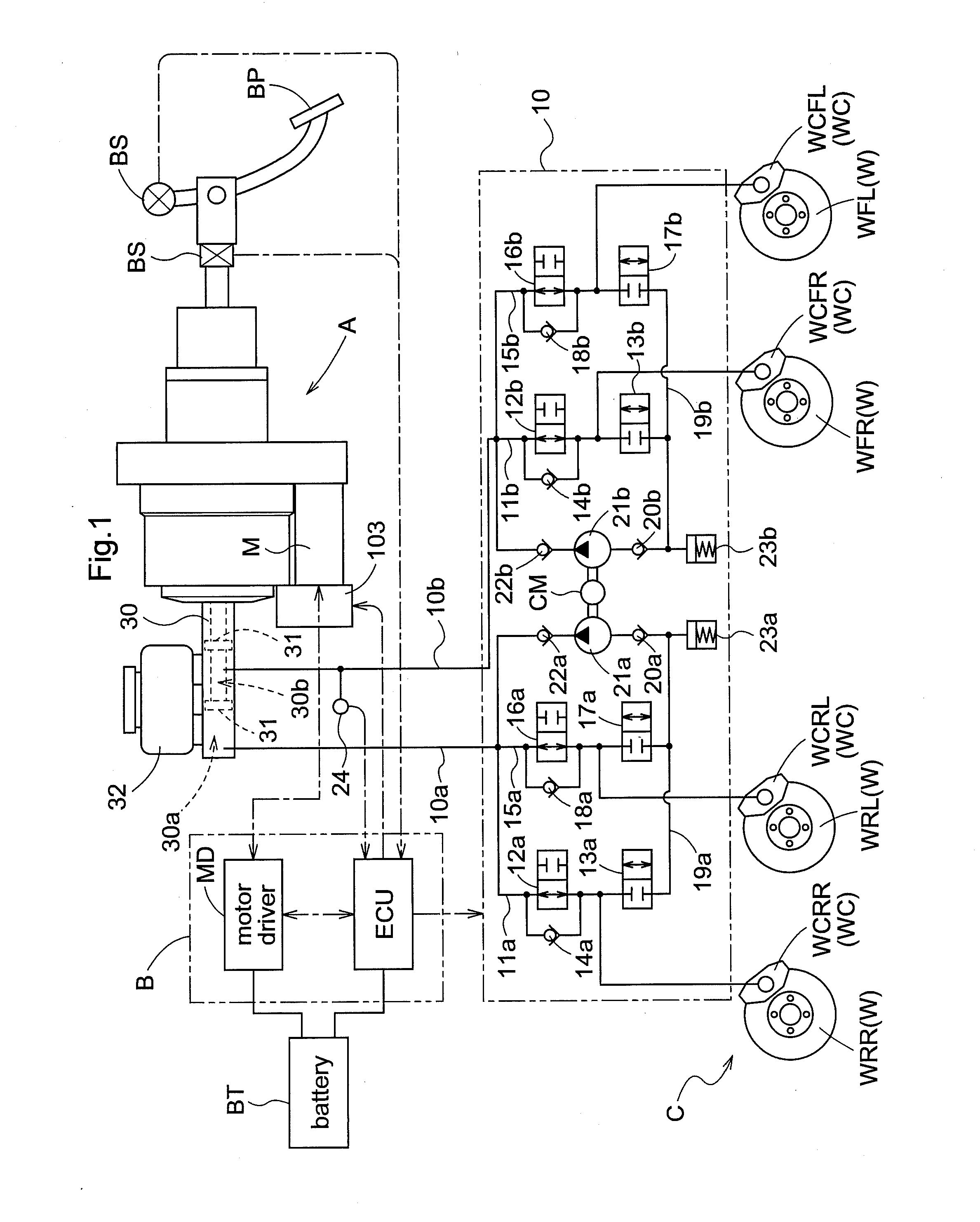
[0035]A first embodiment of a braking device of the present invention will be described with reference to the drawings. The braking device of the present invention includes: a brake operation sensor BS configured to measure an operation amount of a brake pedal BP by a driver; a braking mechanism C actuatableconfigured to be actuated by a fluid pressure and to exert braking forces on wheels W; a hydraulic circuit 10 configured to transmit a fluid pressure to the braking mechanism C; a master cylinder 30 configured to generate a fluid pressure of brake oil in the hydraulic circuit 10; a master reservoir 32 configured to supply the brake oil to the master cylinder 30; a pressurizing mechanism A configured to generate a fluid pressure in the master cylinder 30 in accordance with an operation of the brake pedal BP; and a control unit B configured to apply a current to the pressurizing mechanism A in accordance with a measurement result by the brake operation sensor BS.

[0036]The braking m...

second embodiment

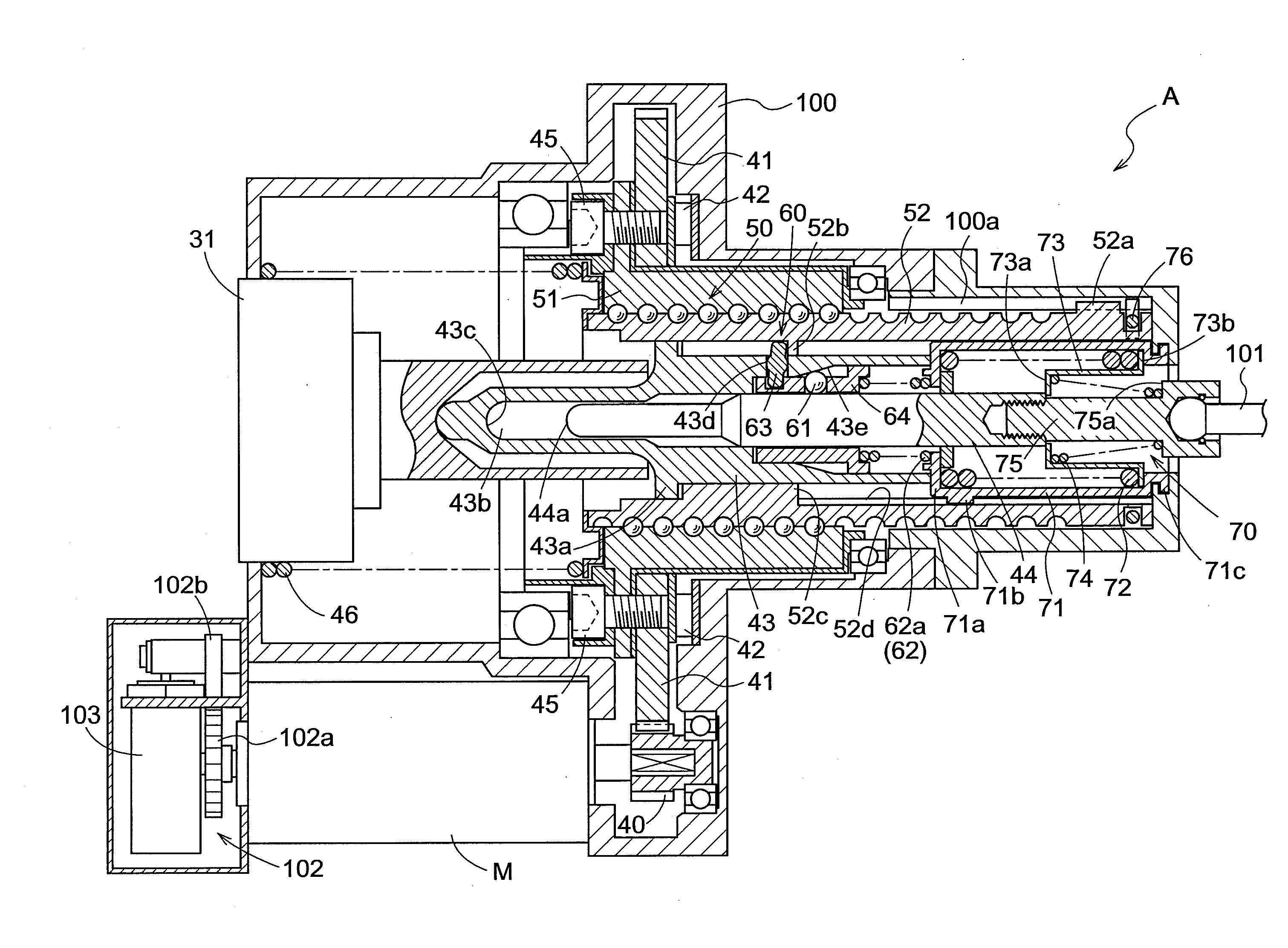
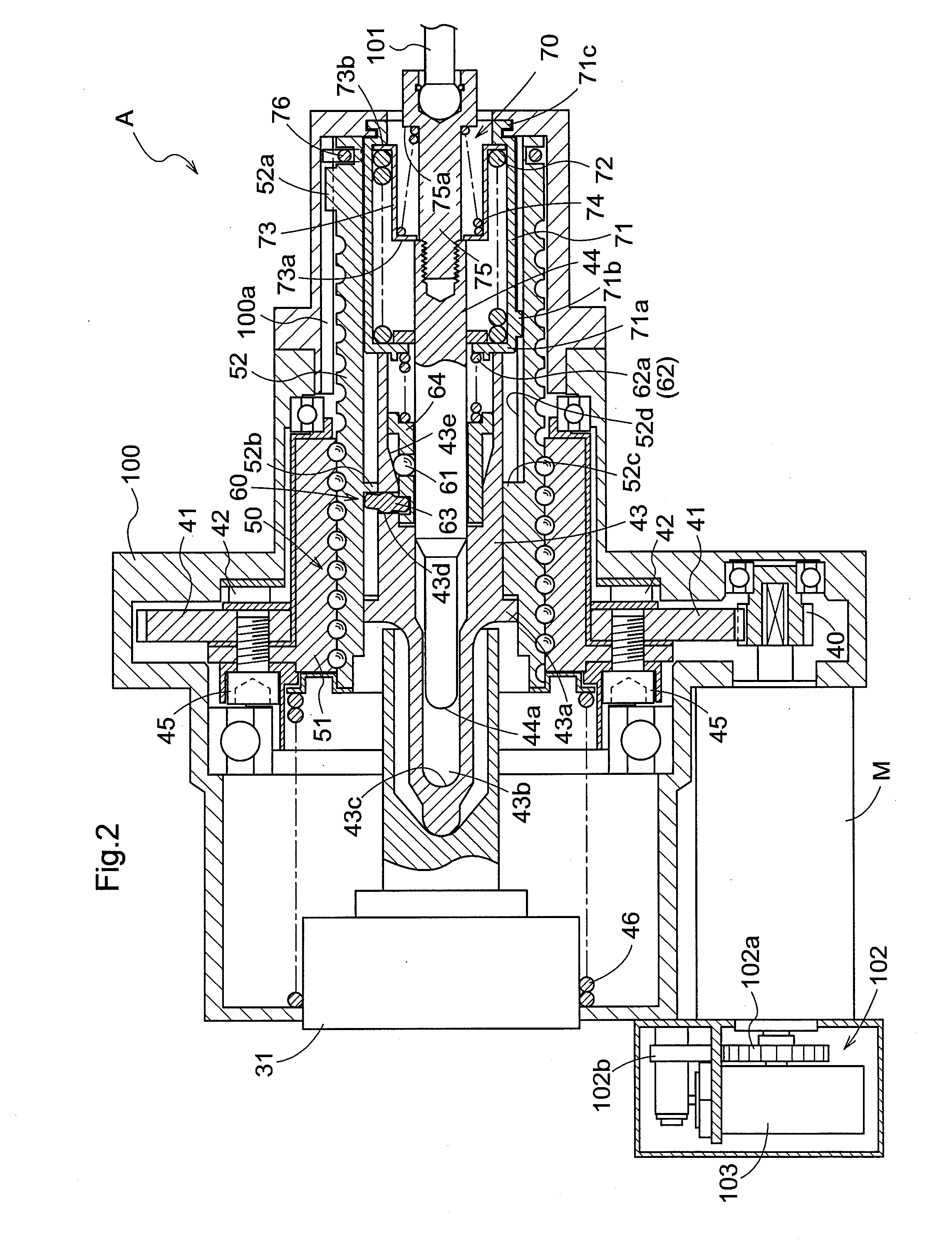
[0077]In the embodiment described above, when the braking device is not actuated, the input rod 44 and the output piston 43 are in a connected state by the function of the clutch mechanism 60. In addition, when the brake operation of emergency or the like is performed, the actuation of the motor M may delay behind the brake operation. In this case, the input rod 44 and the output piston 43 are in a connected state through the clutch mechanism 60, and the stroke simulator 70 is not locked to the housing 100. When the motor M is driven after the advance of the input rod 44, the connection of the input rod 44 and the output piston 43 is cancelled by the clutch mechanism 60. However, since the stroke simulator 70 is not locked to the housing 100, a reaction force is not generated, and an uncomfortable feeling is brought to a driver at this time point. The above-described configuration is provided for solving such a problem, but alternatively, the following control can be preformed in th...

third embodiment

[0084]In the embodiment described above, the biasing element 62 of the clutch mechanism 60 is fixed to the end wall 71a of the first casing 71. However, as shown in FIG. 7, a fixed member 65 may be present on the stroke simulator 70 side relative to the biasing element 62. The fixed member 65 is fixed to the other end of the output piston 43 by a fixing ring 66. In this configuration, the biasing element 62 is pinched between the fixed members 64 and 65 in a compressed state, and thus exerts forces in a stretching direction on both the fixed members 64 and 65. The force on the fixed member 64 serves as a force that biases the rolling element 61 to the tapered face 43e. On the other hand, the force on the fixed member 65 is cancelled out by a reaction force from the fixing ring 66. As a result, it becomes unnecessary to set an initial load of a return spring (not shown) in the master piston 31 to an initial load of the biasing element 62 or more, and thus the tread force during the d...


PUM


Abstract

A braking device includes: an input member configured to interlock with a displacement of a brake pedal; an output member which is movable relatively to and independently of the input member and is configured to generate a fluid pressure in a master cylinder; a braking mechanism configured to exert a braking force on a wheel by the fluid pressure generated in the master cylinder; drive means configured to drive the output member independently of the input member; and a clutch mechanism which is provided between the input member and the output member and configured to engage the input member with the output member so as to allow the input and output members to uniformly move when the output member is not driven by the drive means, and to cancel the engagement between the input member and the output member when the output member is driven by the drive means.

Description

BACKGROUND OF THE INVENTION[0001]1. Field of the Invention[0002]The present invention relates to a braking device for a vehicle, and particularly to a braking device of a brake-by-wire type using an electronic control.[0003]2. Description of the Related Art[0004]Conventionally, for such a braking device for a vehicle, there has been known a technique of Japanese Patent No. 4088802B. The braking device of Japanese Patent No. 4088802B includes: a motor rotatable in forward and reverse directions; a ball screw linearly-moving mechanism configured to convert a rotation of the nut interlocking with the motor into a linear motion in an axial direction of a bolt whose rotation is restricted; a brake operator linked with an rear end of the bolt so as to push the bolt; and a master cylinder having a master piston whose front end is positioned in a hydraulic chamber to which a wheel brake is connected, and whose rear end is linked with a front end of the bolt. In addition, the nut is rotatabl...

Claims


Application Information

Patent Timeline
IPC IPC(8): B60T13/74
CPCB60T1/10B60T13/746B60T8/4077
Inventor ARAKAWA, HARUO
Owner ADVICS CO LTD
Why Eureka
Try Eureka