Bulk Current Injection (BCI) Probe with Multiple, Symmetrically Spaced Feeds

a technology of symmetrical space and probe, which is applied in the direction of instruments, inductances, and reradiation, etc., can solve the problem of little published work on the electromagnetic fields produced by such devices

Active Publication Date: 2010-07-15
TDK CORPARATION
View PDF18 Cites 13 Cited by
  • Summary
  • Abstract
  • Description
  • Claims
  • Application Information

AI Technical Summary

Benefits of technology

[0019]In some embodiments, a power source may be coupled to the plurality of windings for injecting current onto each of the windings. The point at which current is supplied is referred to as the “feed point.” An impedance transforming network may be coupled, in some embodiments, between the power source and the plurality of windings. In one embodiment, the impedance transforming network may comprise an in-phase power divider. In another embodiment, the impedance transforming network may comprise a s

Problems solved by technology

However, little published work exists concerning t

Method used


Image

  • Bulk Current Injection (BCI) Probe with Multiple, Symmetrically Spaced Feeds
  • Bulk Current Injection (BCI) Probe with Multiple, Symmetrically Spaced Feeds
  • Bulk Current Injection (BCI) Probe with Multiple, Symmetrically Spaced Feeds

Examples


Embodiment Construction

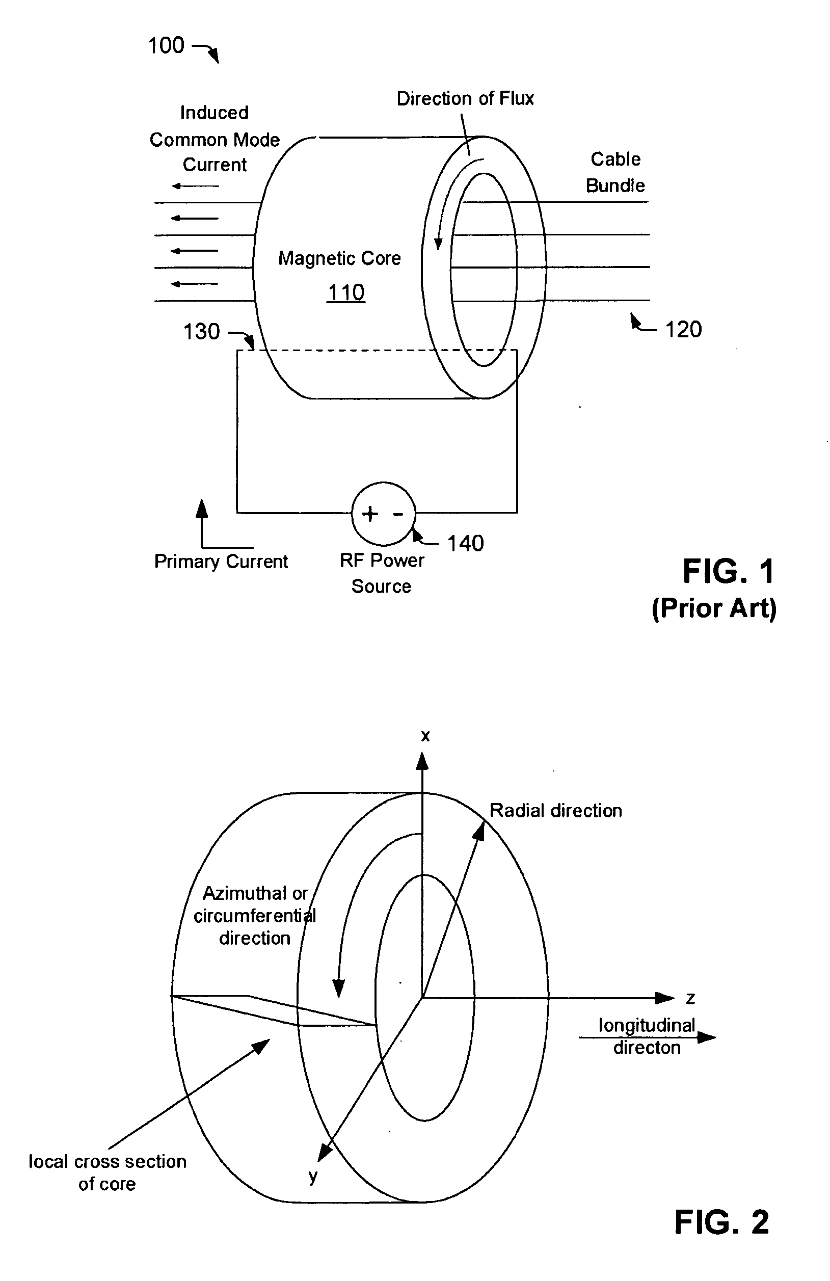
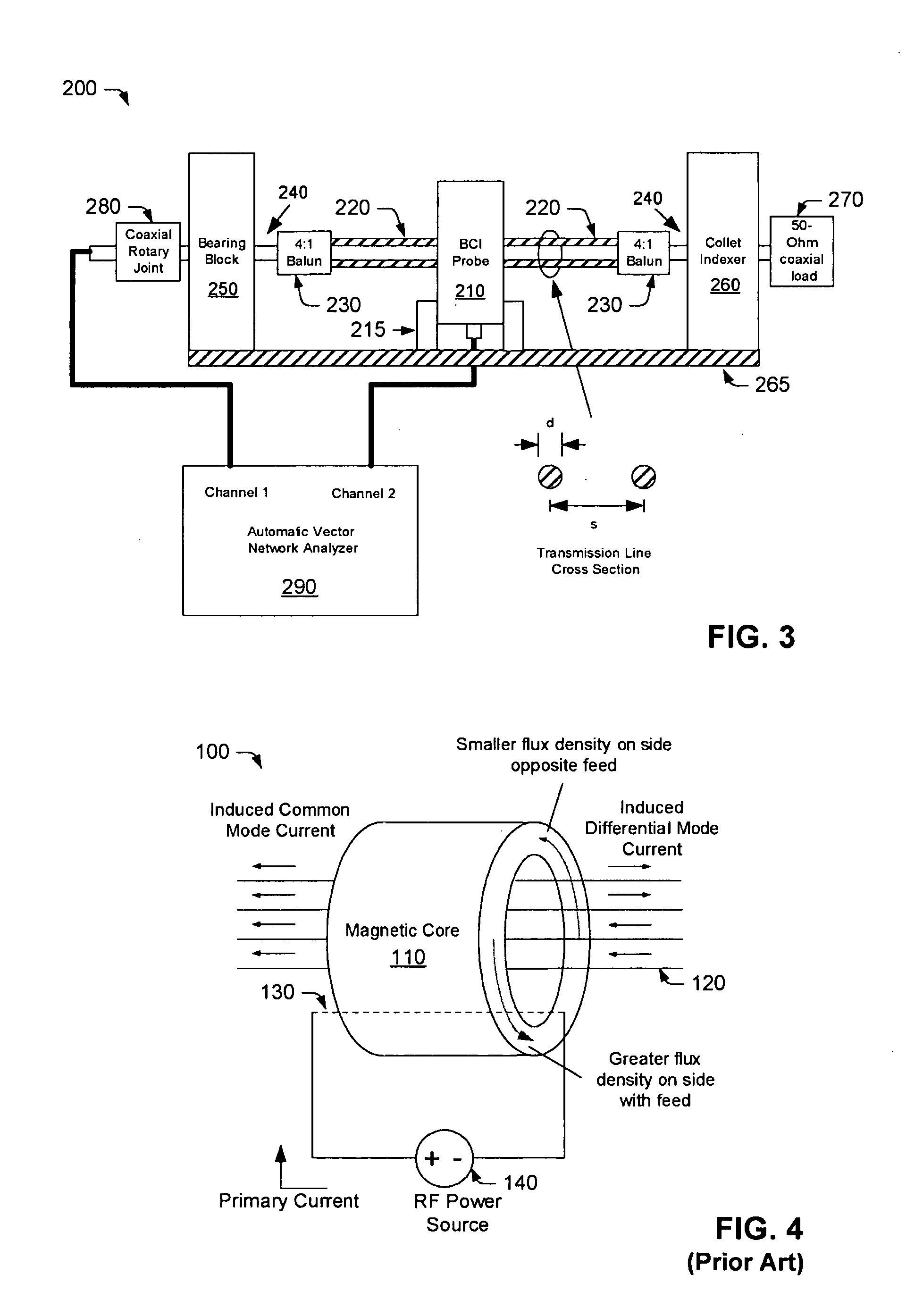
[0038]BCI transformers typically include a magnetic core, which encircles one or more conductors under test, and a magnetic coil, which is wrapped around the core. An RF power source is coupled to the magnetic coil for supplying power to the input or “feed point” of the transformer. When power is supplied, the current flowing through the magnetic coil (the “primary winding”) generates a magnetic flux in an azimuthal direction around the core, which in turn, induces current flow in the conductors under test (the “secondary winding”).

[0039]The magnetic core may comprise substantially any geometry which provides a closed magnetic circuit. As shown in FIG. 2, the magnetic core is often implemented as a cylinder or toroid with a relatively short axial length (compared to its circumferential dimension). In one example, the core may have an outer diameter of about 127 mm, a thickness of about 70 mm and a center hole of about 40 mm (to accommodate the conductors under test). Some transforme...


PUM


Abstract

A Bulk Current Injection (BCI) transformer is provided herein with a magnetic core and a plurality of windings. The magnetic core is configured for encircling one or more electrical conductors under test. Each of the plurality of windings are wrapped, at least in part, around a longitudinal dimension of the magnetic core and spaced apart around an azimuthal dimension of the magnetic core. During injection tests, a power source may be coupled for supplying current to each of the windings at a respective “feed point.” Arranging multiple feed points around the magnetic core enables current flow through the windings to generate an azimuthally-uniform magnetic flux density in the magnetic core. The uniform magnetic flux density enables the BCI transformer to excite only common mode currents in the electrical conductors under test. BCI test methods, including injection tests and current sensing tests are also provided herein, along with a test setup for characterizing BCI transformers.

Description

BACKGROUND OF THE INVENTION[0001]1. Field of the Invention[0002]This invention relates to Bulk Current Injection (BCI) transformers and, more particularly, to BCI transformers with improved magnetic field uniformity, bandwidth and power handling.[0003]2. Description of the Related Art[0004]The following descriptions and examples are given as background only.[0005]Bulk Current Injection (BCI) immunity test methods are often used to evaluate the electromagnetic susceptibility of a wide range of electronic devices. The BCI method injects continuous wave or pulsed current onto the electrical conductor(s) of a device under test (DUT) to mimic the excitation of common mode current on the conductors by far field (plane wave) electromagnetic radiation. BCI tests are desirable because, over a given frequency range, they typically require much less power to produce a specified common mode current on a conductor than a radiated immunity test.[0006]BCI tests use “flux coupled” or Faraday transf...

Claims


Application Information

Patent Timeline
IPC IPC(8): G01R27/02H01F17/04H01F27/36
CPCG01R31/001H01F38/28G01R31/2822
Inventor MCLEAN, JAMES S.SUTTON, ROBERT A.
Owner TDK CORPARATION
Why Eureka
Try Eureka