Coil component and power-supply device provided therewith

Active Publication Date: 2010-07-15
TDK CORPARATION
View PDF2 Cites 19 Cited by
  • Summary
  • Abstract
  • Description
  • Claims
  • Application Information

AI Technical Summary

Benefits of technology

[0012]Therefore, in the coil component of the embodiment, the distance between the first conductor and the second conductor is shortened in the nonmagnetic portion, so that the magnetic coupling between the conductors can be enhanced without providing the large cavity in the magnetic core. Further, because the distance between the first conductor and the second conductor is lengthened in the surface of the magnetic core, a risk of the short circuit between the terminal electrodes is not increased even if the terminal electrodes are provided in the surface of the magnetic core.
[0013]In the coil component, preferably a length of the first and second through-holes from one of the surfaces to the nonmagnetic portion is equal to a length of the first and second through-holes from the other surface to the nonmagnetic portion. Accordingly, because the nonmagnetic portion is located in the central portion of the magnetic core, the same characteristic is obtained even if an input side and an output side are reversed. That is, because the coil component has no directional property, work efficiency can be enhanced when the coil component is mounted.
[0014]The nonmagnetic portion may be a cavity. Accordingly, the production cost of the magnetic core can be suppressed. The nonmagnetic portion maybe an insulating member buried in the magnetic core. Accordingly, the short circuit failure through the nonmagnetic portion can be prevented.
[0015]In the coil

Problems solved by technology

That is, the smooth output current cannot be obtained, when the excessively strong magnetic coupling is generated between the conductors, or when the excessively weak magnetic coupling is generated between the conductors.
However, according to the research of the inventors, it is proved that various problems occur when the magnetic coupling is adjusted only by the length L of the cavity 13a. Specifically, when the length L of the cavity 13a is increased to enhance the magnetic coupling, a volume of the cavity 13a is increased with the length.
However, a distance between the conductors is also shortened when the distance between the grooves 11 and 12 is shortened, which in

Method used


Image

  • Coil component and power-supply device provided therewith
  • Coil component and power-supply device provided therewith
  • Coil component and power-supply device provided therewith

Examples


Embodiment Construction

[0030]Preferred embodiments of the present invention will be explained below in detail with reference to the accompanying drawings.

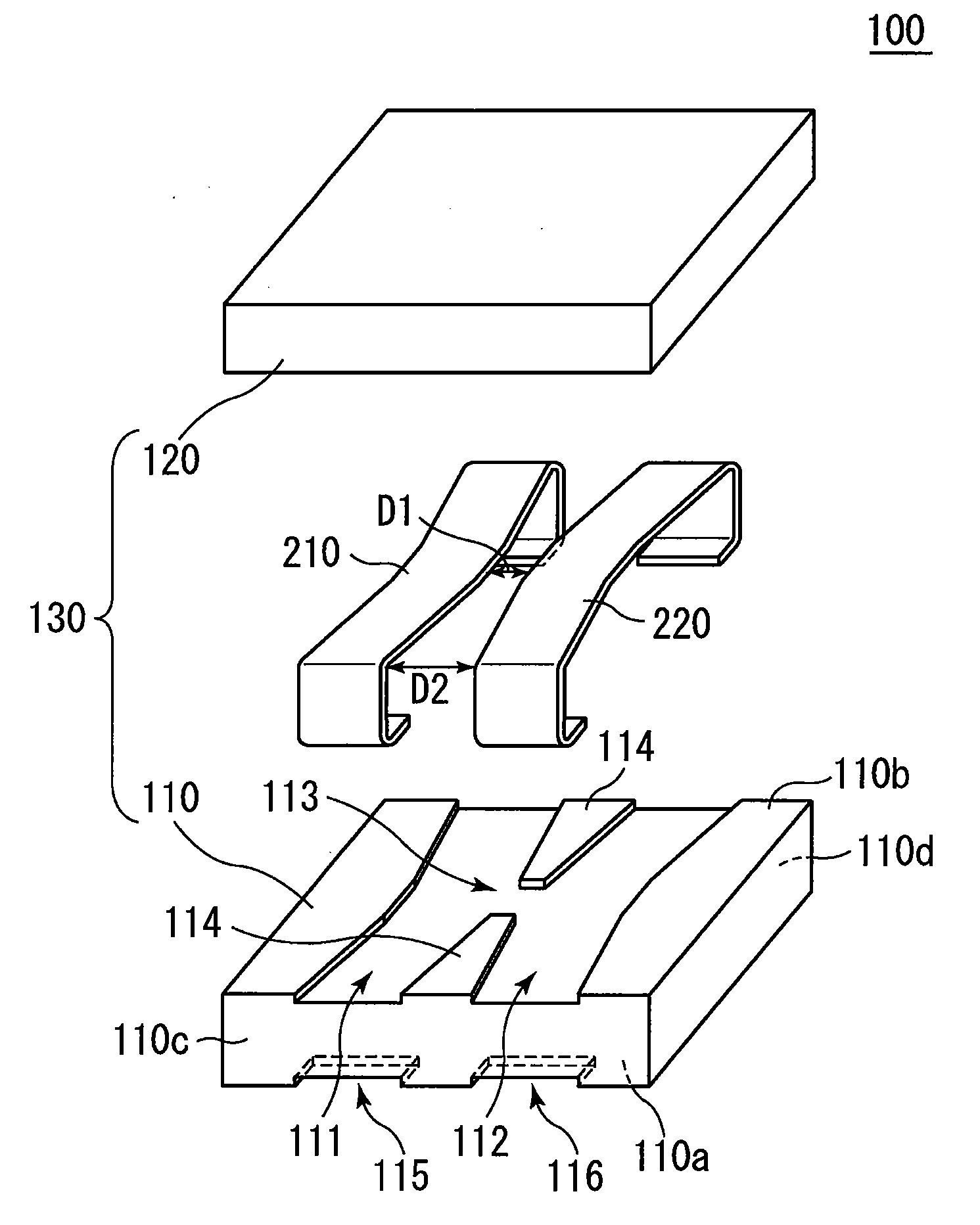
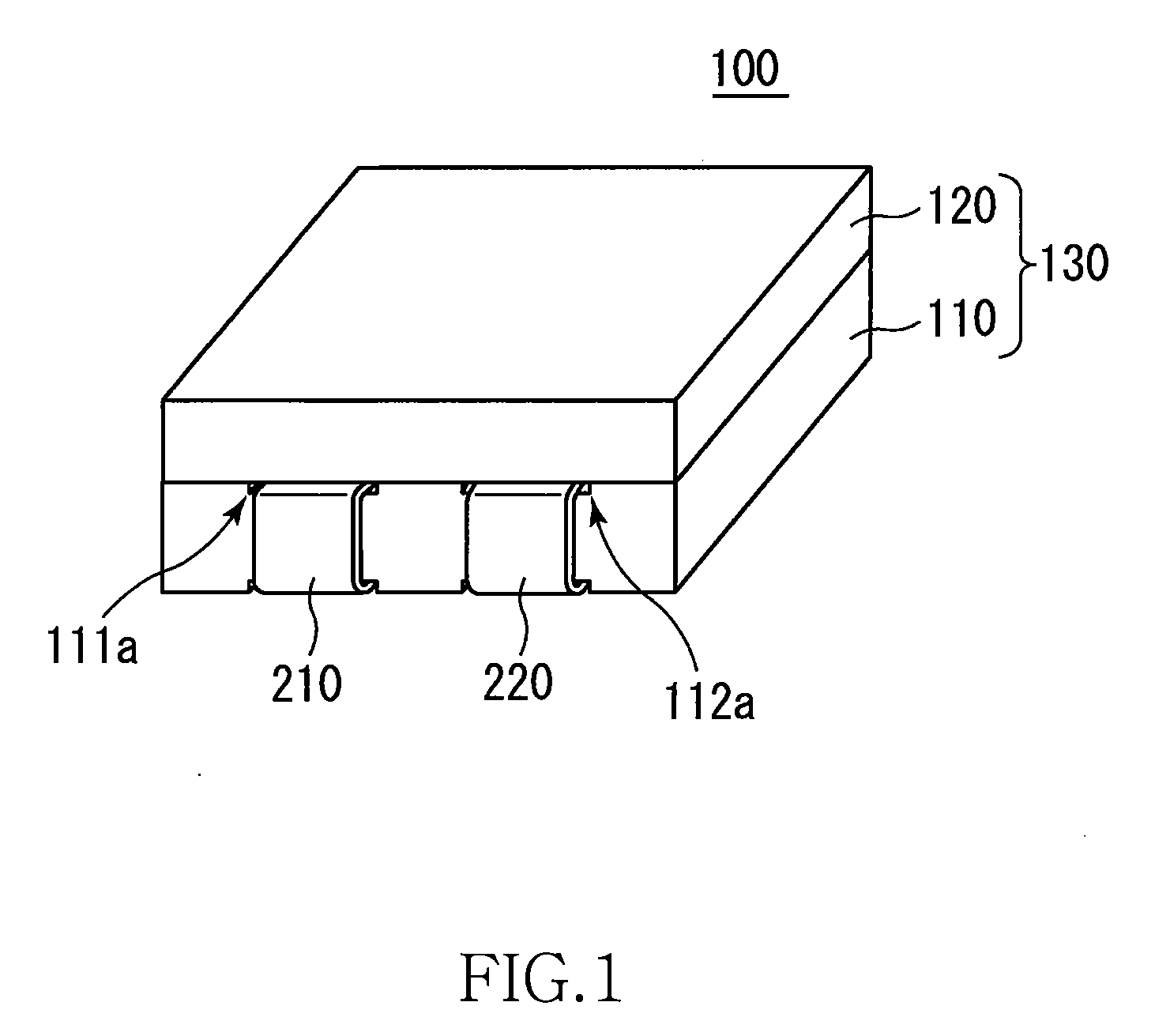
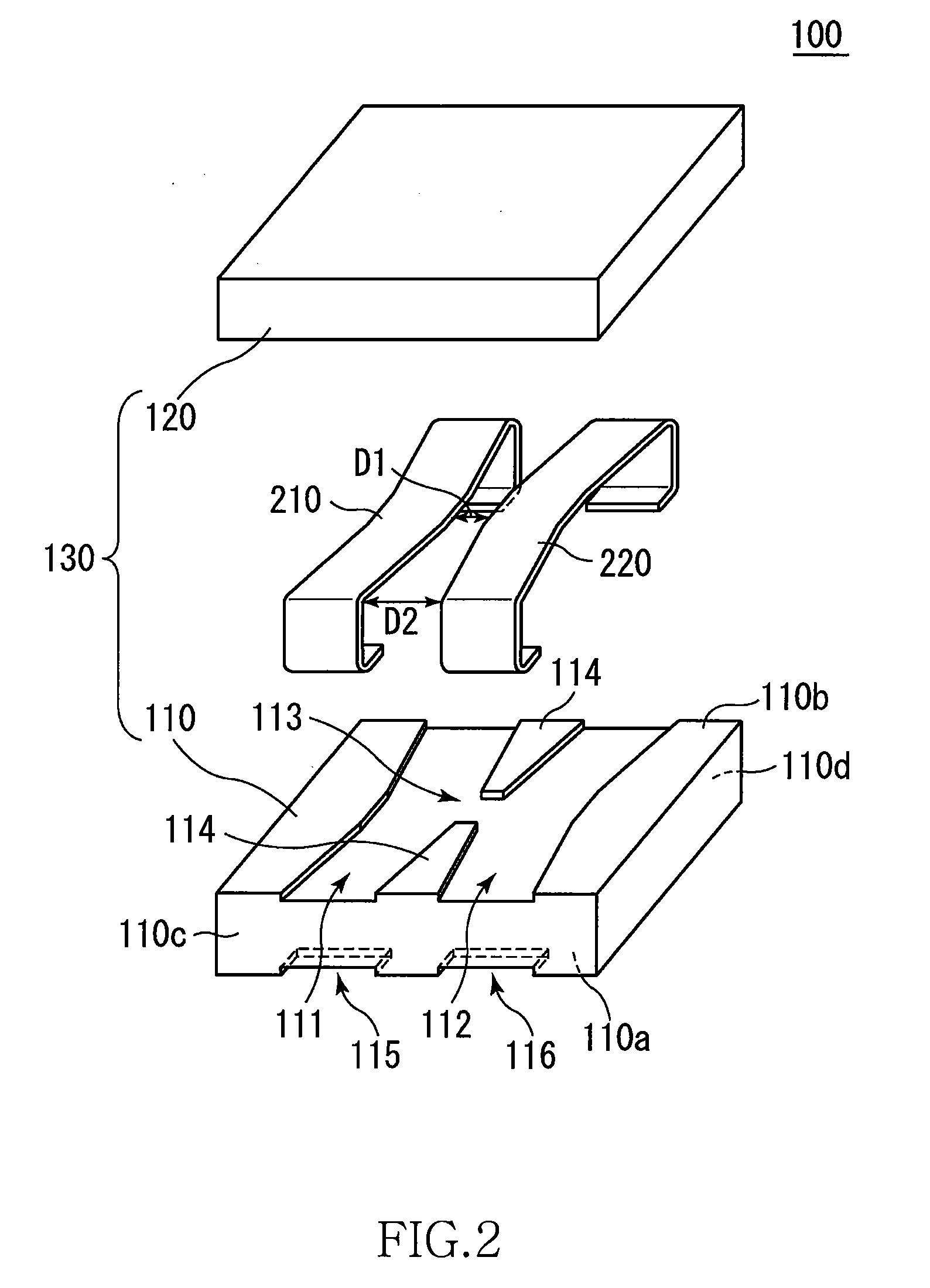
[0031]FIG. 1 is a schematic perspective view illustrating an appearance of a coil component 100 according to an exemplary embodiment of the invention. FIG. 2 is a schematic exploded perspective view of the coil component 100 of the embodiment.

[0032]As illustrated in FIGS. 1 and 2, the coil component 100 of the embodiment includes a magnetic core 130 and first and second conductors 210 and 220. The magnetic core 130 includes first and second magnetic members 110 and 120. Preferably the magnetic members 110 and 120 are made of a Mn—Zn ferrite or a Ni—Zn ferrite. Preferably the conductors 210 and 220 are made of metal such as copper. A high magnetic coupling can be obtained when the magnetic members 110 and 120 are made of the Mn—Zn ferrite. However, because the Mn—Zn ferrite has electrically conductive characteristic, it is necessary to coat the conductors...


PUM


Abstract

The coil component includes a magnetic core 130 and conductors 210 and 220. The magnetic core 130 includes through-holes that are made by grooves 111 and 112. The conductors 210 and 220 are provided in the grooves 111 and 112, respectively. The magnetic core 130 includes a nonmagnetic portion in which the grooves 111 and 112 are communicated, and a distance between the conductors 210 and 220 through the nonmagnetic portion is shorter than a distance between the conductors 210 and 220 in surfaces 110c and 110d in which the conductors 210 and 220 are exposed. Therefore, necessity to provide a large cavity in the magnetic core is eliminated, and a risk of the short circuit between terminal electrodes exposed in the surfaces 110c and 110d is also eliminated.

Description

BACKGROUND OF THE INVENTION[0001]1. Field of the Invention[0002]The present invention relates to a coil component, particularly to a coil component that is suitably used as a coupled inductor of a power-supply device. The invention also relates to a power-supply device provided with the coil component.[0003]2. Description of Related Art[0004]A so-called multi-phase regulator circuit is known as one of power-supply devices used in a computer and the like. In the multi-phase regulator circuit, switching currents having different phases are produced by switching, and a smooth output current is obtained by combining the switching currents. In the multi-phase regulator circuit, a coil component called a coupled inductor may be used in order to smooth output current. For example, Japanese Patent Application Laid-Open No. 2007-184509 discloses a coupled inductor.[0005]In order to smooth output current by the coupled inductor, it is necessary that a magnetic coupling be generated at a desir...

Claims


Application Information

Patent Timeline
IPC IPC(8): H01F27/24
CPCH01F3/12H01F17/06H01F27/006H02M7/003H01F27/292H01F2038/006H01F27/2847
Inventor YASUDA, KATSUHARUFUJIWARA, KIYOFUMISHINDO, MASATOSHI
Owner TDK CORPARATION
Why Eureka
Try Eureka