Tamper respondent module

a technology of tamper response and electronic modules, applied in the direction of printed circuit aspects, internal/peripheral component protection, emergency protective arrangements for limiting excess voltage/current, etc., can solve the problems of detectable variation and detectable variation

Inactive Publication Date: 2010-07-15
DY 4 SYST
View PDF25 Cites 123 Cited by
  • Summary
  • Abstract
  • Description
  • Claims
  • Application Information

AI Technical Summary

Benefits of technology

[0006]The following presents a simplified summary of the invention in order to provide a basic understanding of some example aspects of the invention. This summary is not an extensive overview of the invention. Moreover, this summary is not intended...

Problems solved by technology

Damage to the anti-tamper apparatus results in a detectable variation of the electromagnetic energy distribution of the anti-tamper apparat...

Method used


Image

  • Tamper respondent module
  • Tamper respondent module
  • Tamper respondent module

Examples


Embodiment Construction

[0019]Example embodiments that incorporate one or more aspects of the present invention are described and illustrated in the drawings. These illustrated examples are not intended to be a limitation on the present invention. For example, one or more aspects of the present invention can be utilized in other embodiments and even other types of devices. Moreover, certain terminology is used herein for convenience only and is not to be taken as a limitation on the present invention. Still further, in the drawings, the same reference numerals are employed for designating the same elements.

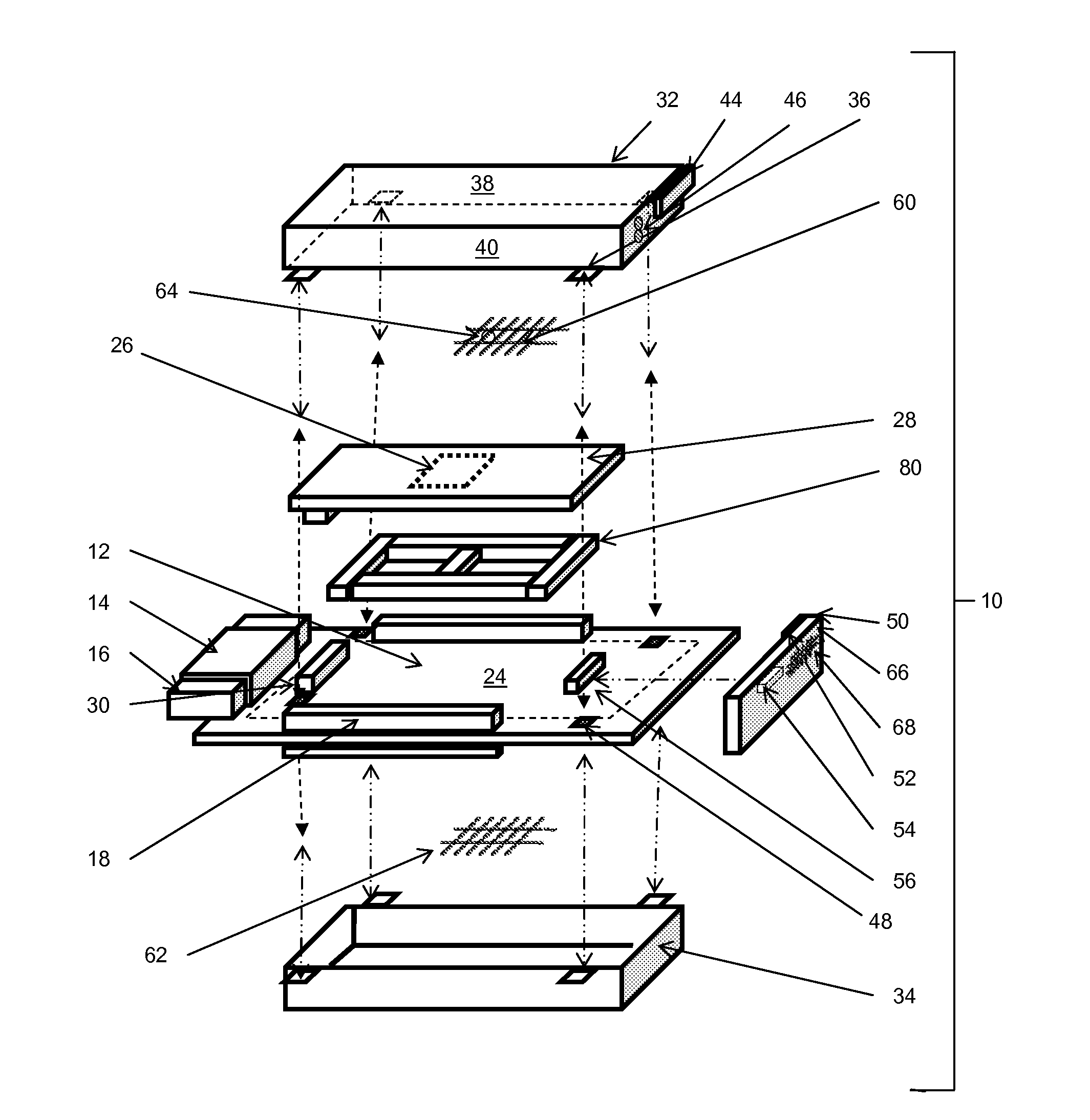
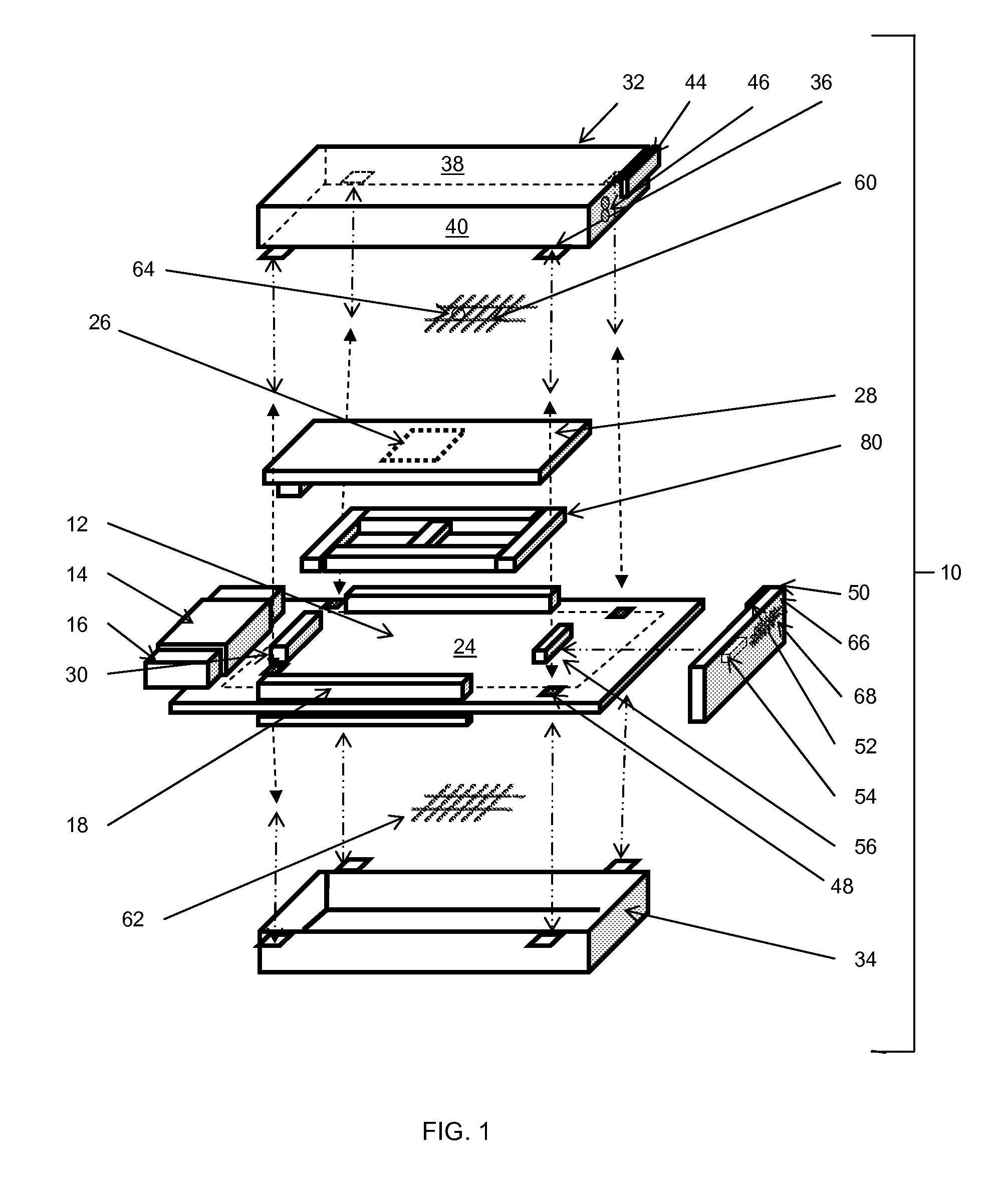
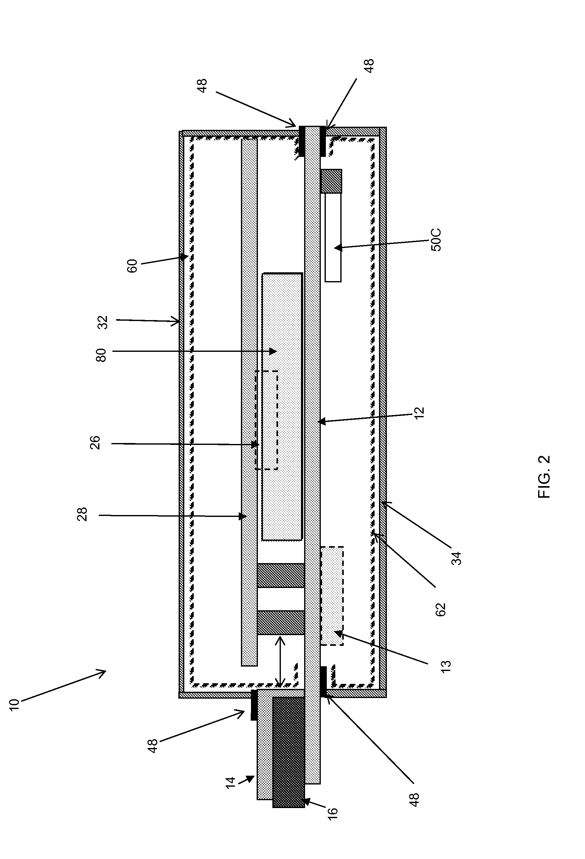
[0020]The module in this application enables a modular physical anti-tamper (“AT”) security solution for electronics used in harsh environments for standards based 3U and 6U VPX (VITA-46) formats as well as VITA-48 formats not readily available with past commercial off the shelf (COTS) solutions. This application also enables systems integrators and their end customers to achieve highest levels of FIPS-1...


PUM


Abstract

A tamper respondent module includes a basecard adapted to be inserted into a slot in a rack enclosure comprising at least one guide edge, at least one electrical coupler, a surface and at least one electronic component that contains information in an electronic format. In one example, an outer cover is coupled to the basecard and includes at least five sides. The outer cover is arranged in a covering relationship over the at least one electronic component. In another example, an anti-tamper apparatus is disposed between the outer cover and the surface. In another example, an anti-tamper circuit is electrically coupled to the at least one electronic component. In another example, a thermal frame is thermally coupled to the at least one electronic component.

Description

CROSS-REFERENCE TO RELATED APPLICATIONS[0001]This application claims the benefit of U.S. Provisional Application No. 61 / 144,200, filed Jan. 13, 2009, the entire disclosure of which is hereby incorporated herein by reference.FIELD OF THE INVENTION[0002]The present invention relates generally to an electronic module, and more particularly, to an electronic module with anti-tamper features.BACKGROUND OF THE INVENTION[0003]Electronic modules often store highly sensitive information. For example, communication devices can store cryptographic keys, handhelds can store passwords and records, and embedded systems can hold sensitive algorithms or information in memory. These devices can easily fall into the wrong hands.[0004]It is conceivable that an attack on a device or installation to obtain information may be mounted in several stages, including but not limited to: 1. Removal of covers or covers and any encapsulant; 2. Identification of the location and function of security sensors; 3. B...

Claims


Application Information

Patent Timeline
IPC IPC(8): H05K1/14
CPCG06F21/86H05K1/0275H05K2201/10151H05K5/0208H05K1/141
Inventor ARSHAD, NAUMANKWOK, JINGSTRAZNICKY, IVANCASSELS, MARTIN TERENCE
Owner DY 4 SYST
Why Eureka
Try Eureka