Advanced method for decoding in the mimo system and apparatus for implementing thereof

a technology of mimo and decoding method, applied in the field of radio communication, can solve the problems of significant reduction in its effectiveness, strict computational resources, and significantly lower complexity of such a method than the ml method, and achieve the effect of less strict computational resources

Inactive Publication Date: 2010-07-15
SAMSUNG ELECTRONICS CO LTD
View PDF7 Cites 12 Cited by
  • Summary
  • Abstract
  • Description
  • Claims
  • Application Information

AI Technical Summary

Benefits of technology

[0021]To address the above-discussed deficiencies of the prior art, it is a primary object to provide an improved method for detecting a signal in the MIMO system, which method possesses an accuracy close to the maximum likelihood technique, but less strict to the computational resources, and, second, in developing an apparatus for implementing such a method.

Problems solved by technology

However, this scheme includes a significant reduction in its effectiveness due to the maximum likelihood (ML) scheme that provides soft solutions, but is very strict to the computational resources.
The disadvantage of the closest analogue consists in that, whereas the complexity degree of such a method is significantly lower than of the ML method, it is still nevertheless very high, especially in the case when the number of the Tx and Rx antennas is great.

Method used


Image

  • Advanced method for decoding in the mimo system and apparatus for implementing thereof
  • Advanced method for decoding in the mimo system and apparatus for implementing thereof
  • Advanced method for decoding in the mimo system and apparatus for implementing thereof

Examples


Embodiment Construction

[0031]FIGS. 1 through 5, discussed below, and the various embodiments used to describe the principles of the present disclosure in this patent document are by way of illustration only and should not be construed in any way to limit the scope of the disclosure. Those skilled in the art will understand that the principles of the present disclosure may be implemented in any suitably arranged system.

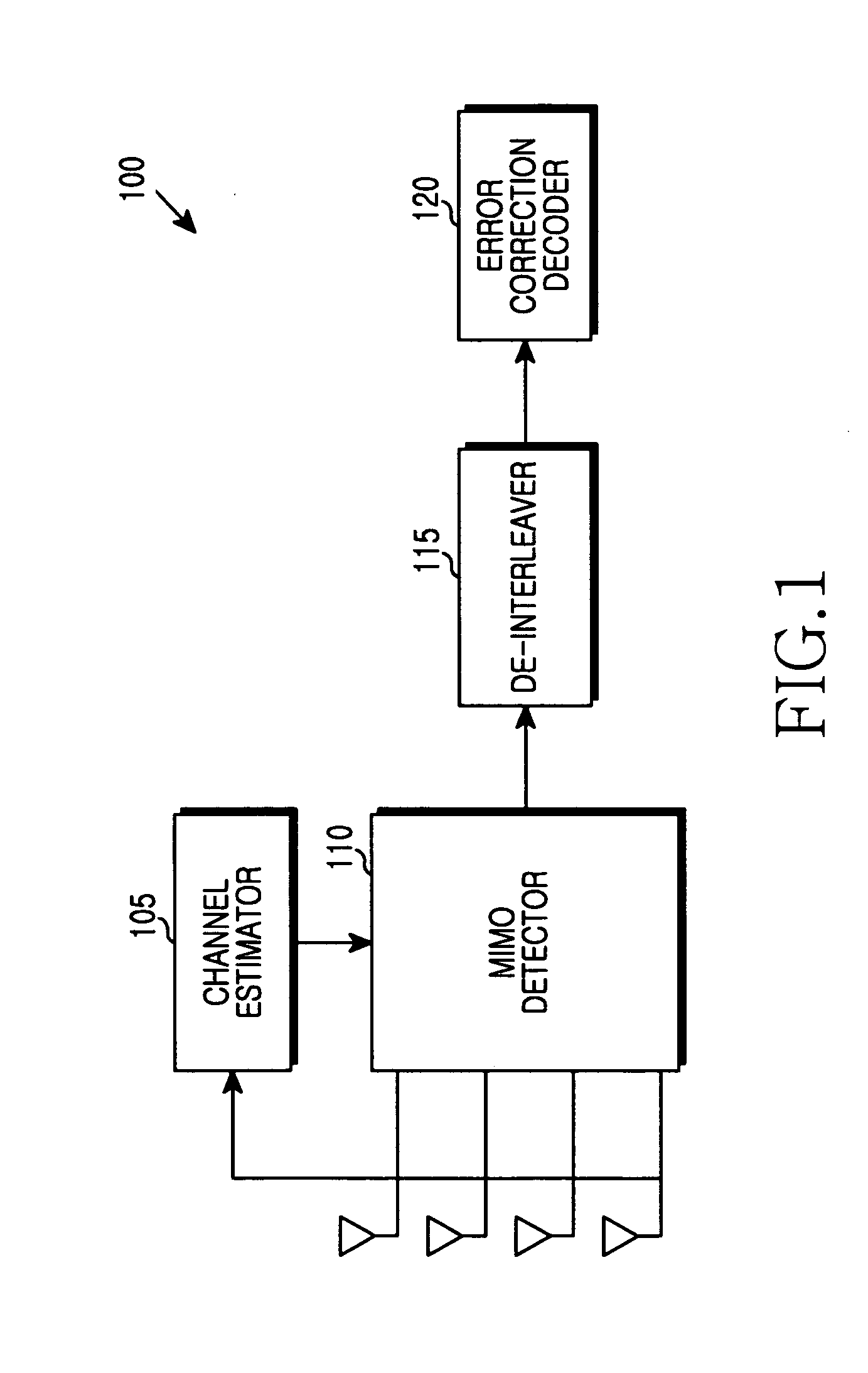
[0032]FIG. 1 illustrates a block diagram of the MIMO receiver.

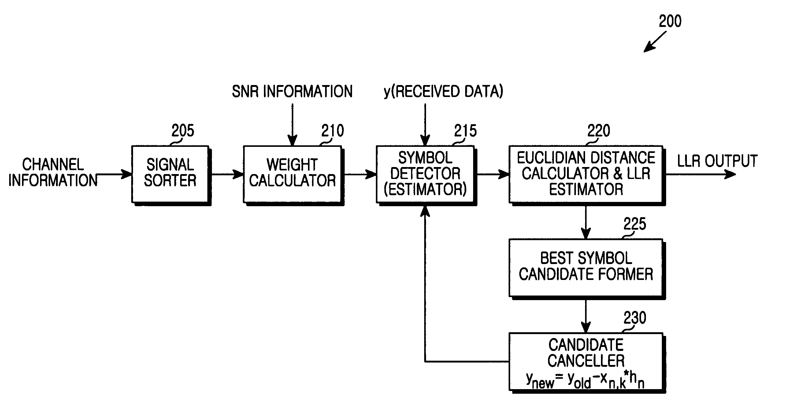
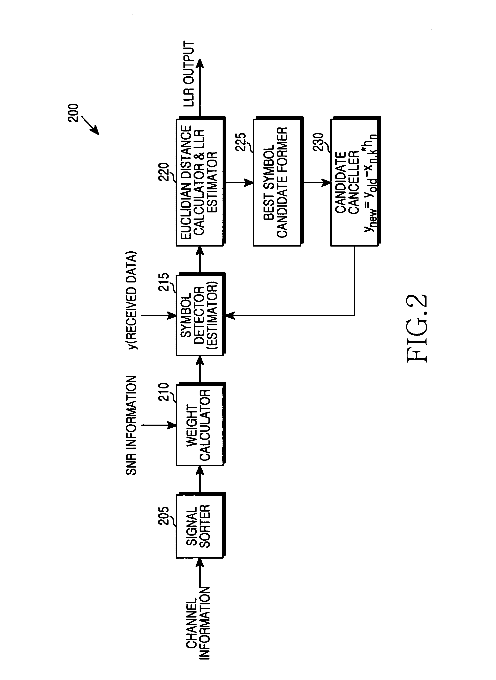
[0033]Referring to FIG. 1, the MIMO receiver 100 comprises a channel estimator 105, a MIMO detector 110, a de-interleaver 115 and an error correction decoder 120. The channel estimator 105 estimates signals from multiple antennas and provides estimation results to the MIMO detector 110. The MIMO detector 110 will be explained in FIG. 2. The de-interleaver 115 performs de-interleaving data provided from the MIMO detector 110. The error correction decoder 120 performs decoding data provided from the de-interleaver 115.

[0034]The bloc...


PUM


Abstract

A mobile station is capable of detecting a signal in the wireless communication systems using the Multiple Input Multiple Output (MIMO). The mobile station includes an apparatus that determines a vector of signals received by several receiving antennas. The apparatus estimates a channel between transmitting antenna and receiving antenna; forms a channel matrix; establishes, based on the channel state data, an order for detecting symbols transmitted by different transmitting antennas; calculates weight coefficients for detecting the symbols in the MIMO system; detects the symbols serially in the established order on the basis of the received signal vector; calculates the Euclidean distance between the detected symbols and the symbol constellation points; determines values of the Logarithmic Likelihood Ratio (LLR) for estimating the soft output bit probability, and forms a group of the most probable candidate symbols from the points of the symbol constellation.

Description

CROSS-REFERENCE TO RELATED APPLICATION(S) AND CLAIM OF PRIORITY[0001]The present application is related to and claims priority to an application entitled “ADVANCED METHOD FOR DECODING IN THE MIMO SYSTEM AND APPARATUS FOR IMPLEMENTING THEREOF” filed in the Russian Patent Office on Jan. 12, 2009 and assigned Serial No. 2009100150, the contents of which are incorporated herein by reference.TECHNICAL FIELD OF THE INVENTION[0002]The present application relates generally to the radio communication field and particularly to the wireless communication systems using the Multiple Input Multiple Output (MIMO) principle and decoding technique based on the Ordered Successive Interference Cancellation (OSIC).BACKGROUND OF THE INVENTION[0003]An effective signal detection tool is necessary for a high-quality communication in the MIMO-system. Specifically, a V-BLAST detection scheme, as disclosed in P. W. Wolniansky, G. J. Foschini, G. D. Golden, and R. A. Valenzuela, “V-BLAST: an architecture for r...

Claims


Application Information

Patent Timeline
Patent Type & Authority Applications(United States)
IPC IPC(8): H04B7/02
CPCH04L1/0631H04B7/0857H04L25/0202
Inventor LEONIDOVICH, ROG ANDREYOLEGOVICH, MELNIKOV ALEXEYVICTOROVICH, CHERNYSH ALEXANDERVLADIMIROVICH, GOLIKOV MICHAELCHOI, SOONGYOON
Owner SAMSUNG ELECTRONICS CO LTD
Why Eureka
Try Eureka