
Small-diameter deep hole drill and a micro deep hole drilling method

Inactive Publication Date: 2010-07-15
HITACHI TOOL ENG LTD
View PDF6 Cites 10 Cited by
  • Summary
  • Abstract
  • Description
  • Claims
  • Application Information

AI Technical Summary

Benefits of technology

[0036]Using the present invention, it becomes possible to drill a deep hole having an L / D ratio of 15 or more, obtaining an acceptable roughness of hole inner surface without unevenness or the like, as well as an excellent straightness.
[0037]Further, using the present invention, it becomes possible to realize a long life for the small-diameter deep hole drill by combining the new drill shape with the new drilling method.
[0038]In addition, when applied to a drilling process for forming a through hole, the present invention can greatly improve an inner surface roughness of the drilled micro deep hole and ensure an acceptable straightness. Accordingly, it becomes possible to omit a reaming process which was otherwise often necessary after a drilling process in prior art, thereby rendering it possible to perform a micro deep hole drilling for drilling a through hole in only one process using only one drill.

Problems solved by technology

Therefore, a tool deflection occurs during a drilling process, resulting in a deterioration of the straightness of a drilled hole or a breakage of the drill.

Method used


Image

  • Small-diameter deep hole drill and a micro deep hole drilling method
  • Small-diameter deep hole drill and a micro deep hole drilling method
  • Small-diameter deep hole drill and a micro deep hole drilling method

Examples


embodiments

[0158]Now, description will be given to explain Example 1 which evaluates the straightness as a basic effect of the present invention.

example 1

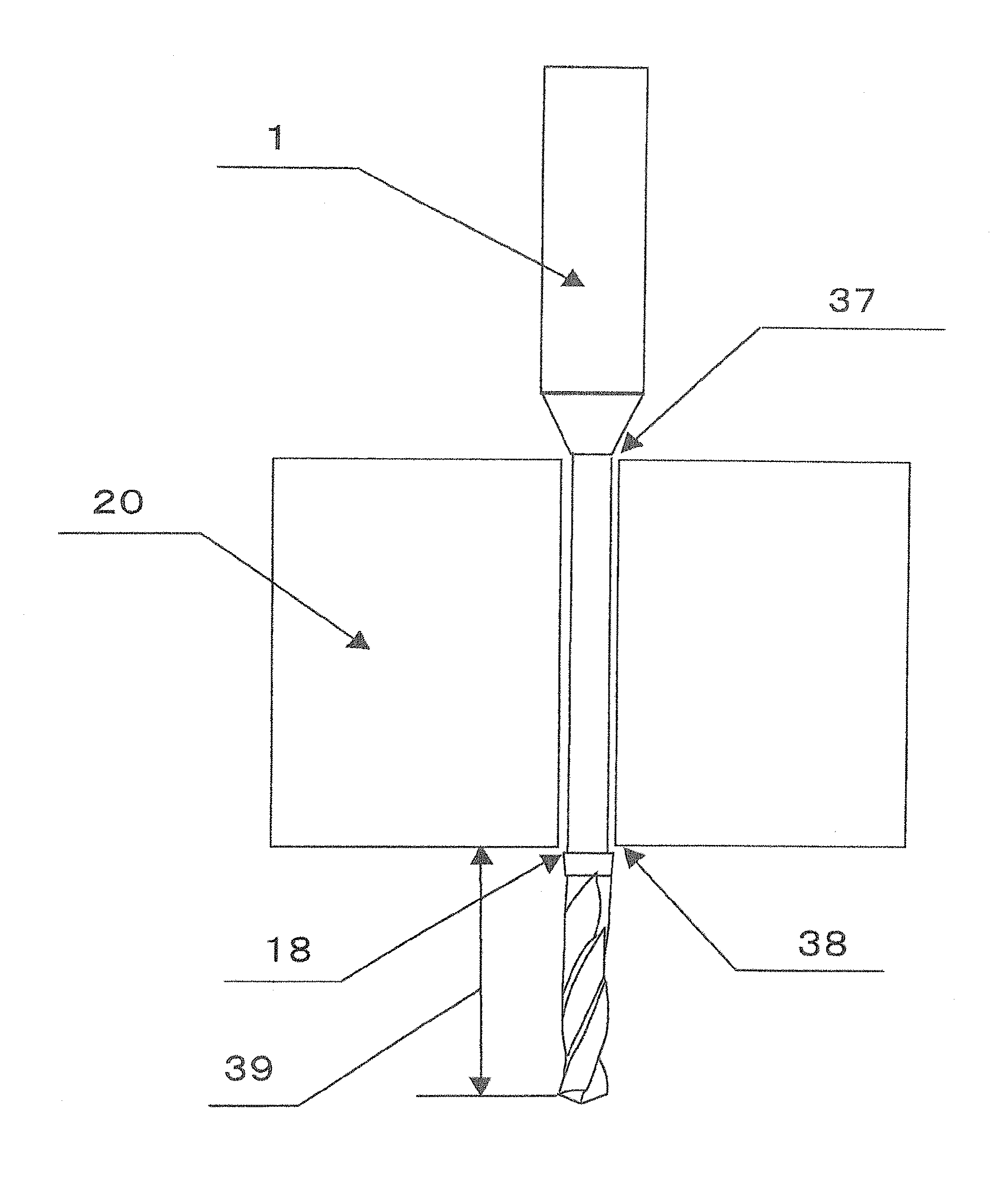
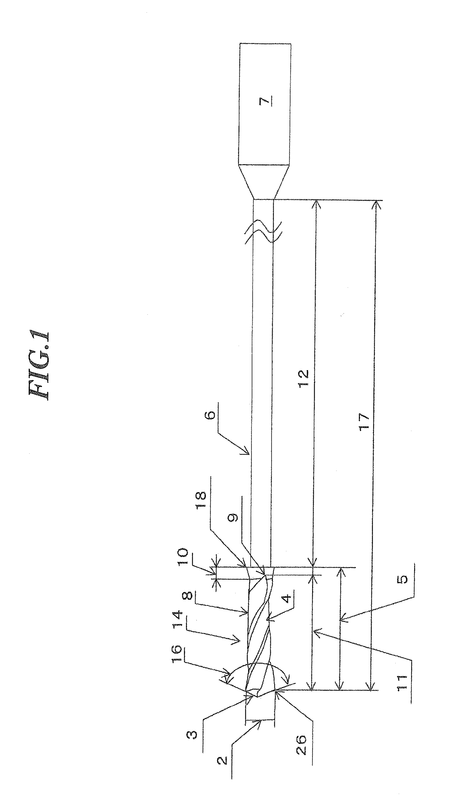
[0159]As examples of the present invention and comparative examples, each drill is provided with two cutting edges, having a drill diameter of 0.2 mm, a flute helix angle of 30 degrees, a web thickness of 0.07 mm (35% of the drill diameter), a shank diameter of 3 mm, and a drill section length 5 of 1.1 mm. Various parameters are shown in Table 1, including flute length, diameter reduction of outer diameter (back tapering amount), outer diameter at flute end, and maximum diameter of straightly tapered expanded-diameter portions. In Table 1, flute length, outer diameter at flute end, and maximum diameter of straightly tapered expanded-diameter portion are each expressed as a ratio with respect to the drill diameter. A base material for each drill is an ultra-fine-grained cemented carbide in which the average particle size of WC is 0.6 μm or less and Co content is 13 w %, with the drill section and the neck section being covered with an AlCrN coating.

[0160]As test condition, SUS304 rec...

example 2

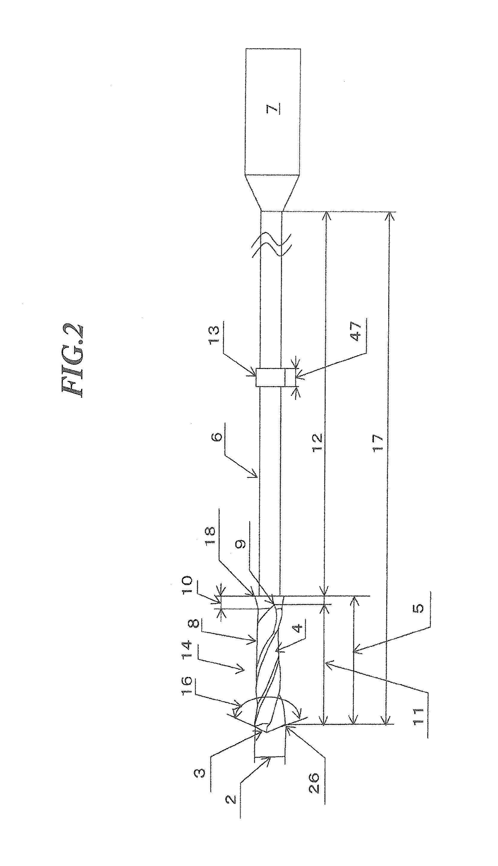
[0164]As examples of the present invention and comparative examples, each drill was provided with two cutting edges, having a drill diameter of 0.2 mm, a drill section of 1.1 mm, a neck section length of 9, 0 mm, an overall length of 40 mm, a flute helix angle of 30 degrees, a web thickness of 0.07 mm (35% of the drill diameter), a shank diameter of 3 mm, and a guide portion located 2.0 mm from the cutting edge of the neck section. Various samples were prepared having different neck section outer diameters, guide portion outer diameters, guide portion lengths, flute lengths, outer diameter reductions (back tapering amount), flute end outer diameters, and maximum diameters of the straightly tapered expanded-diameter portion, as shown in Table 1. A base material for each drill is an ultra-fine-grained cemented carbide in which the average particle size of WC was 0.6 μm or less and Co content was 13 w %, with the drill section and the neck section being covered with an AlCrN coating.

[0...


PUM

PropertyMeasurementUnit
Lengthaaaaaaaaaa
Diameteraaaaaaaaaa
Speedaaaaaaaaaa

Abstract

A small-diameter drill for deep hole drilling is provided which is capable of inhibiting the cutting chips from getting bitten and producing a straightness for a drilled hole, thus suitable for drilling a hole having a depth (L) which is 15 or more times the diameter (D) of a drilled hole. The small-diameter drill 1 has a diameter 2 which is 1 mm or less and a drill section 5 including cutting edge(s) 3 and flute(s) 4. The length 11 of the flute 4 is at least 5 times and at most 10 times the drill diameter 2. The diameter of the drill section 5, after being reduced in diameter from the cutting edge 3 toward the rear of the drill section 5, is expanded in diameter so that the outer diameter at the end of the flute 4 becomes at least 0.9 times and at most 0.98 times the drill diameter 2. An expanded-diameter portion 10 is provided between the drill section 5 and a neck section 6 connected to a shank 7 and is expended in diameter from the outer diameter at the end 9 of the flute 4 up to 1 or less times the drill diameter 2. The diameter of the neck section 6 is smaller than the drill diameter 2, and the length 12 of the neck section 6 is 10 or more times the drill diameter 2.

Description

TECHNICAL FIELD [0001]The present invention relates to a new shape small-diameter deep hole drill having a drill diameter of 1 mm or less, which is for use in processing a die or parts and the like. The invention also relates to a micro deep hole drilling method which uses the small-diameter drill for drilling deep holes with an acceptable precision, especially when a drilled hole diameter (hereafter referred to as “D”) is 1 mm or less and a ratio of the drilled hole diameter to a drilled hole depth (hereafter referred to as “L”) represented by L / D is 15 or more, or when forming a deep through-hole having an L / D ratio of 10 or more, particularly when forming an extremely deep hole having an L / D ratio of 50 or more. Therefore, the present invention relates to a small-diameter drill for deep hole drilling and a micro deep hole drilling method, suitable for forming both micro deep blind holes and through-holes.BACKGROUND [0002]When an over-hang length for a tool to stick out is long wi...

Claims


Application Information

Patent Timeline
IPC IPC(8): B23B51/02B23B41/02B23B35/00
CPCB23B35/00Y10T408/23B23B2251/245B23B2251/248B23B2251/422B23B2251/426B23B2251/54B23B2251/56B23B2270/56Y10T409/303808Y10T408/9095Y10T408/9097Y10T408/03Y10T408/5586B23B51/02B23B51/0411B23B51/063B23B51/011B23B51/00B23B39/00B23B41/00
Inventor KONDOH, YOSHIHIROAKAMATSU, TAKESHI
Owner HITACHI TOOL ENG LTD
Learn More