
Small-diameter deep hole drill and a micro deep hole drilling method
a deep hole drilling and micro technology, applied in the direction of twist drills, manufacturing tools, wood boring tools, etc., can solve the problems of deterioration of the straightness of the drilled hole or a breakage of the drill bit, and achieve the improvement of the inner surface roughness of the drilled micro deep hole, and the straightness of the hole. , the effect of excellent straightness
- Summary
- Abstract
- Description
- Claims
- Application Information
AI Technical Summary
Benefits of technology
Problems solved by technology
Method used
Image

Examples
embodiments
[0159]Now, description will be given to explain Example 1 which evaluates the straightness as a basic effect of the present invention.
example 1
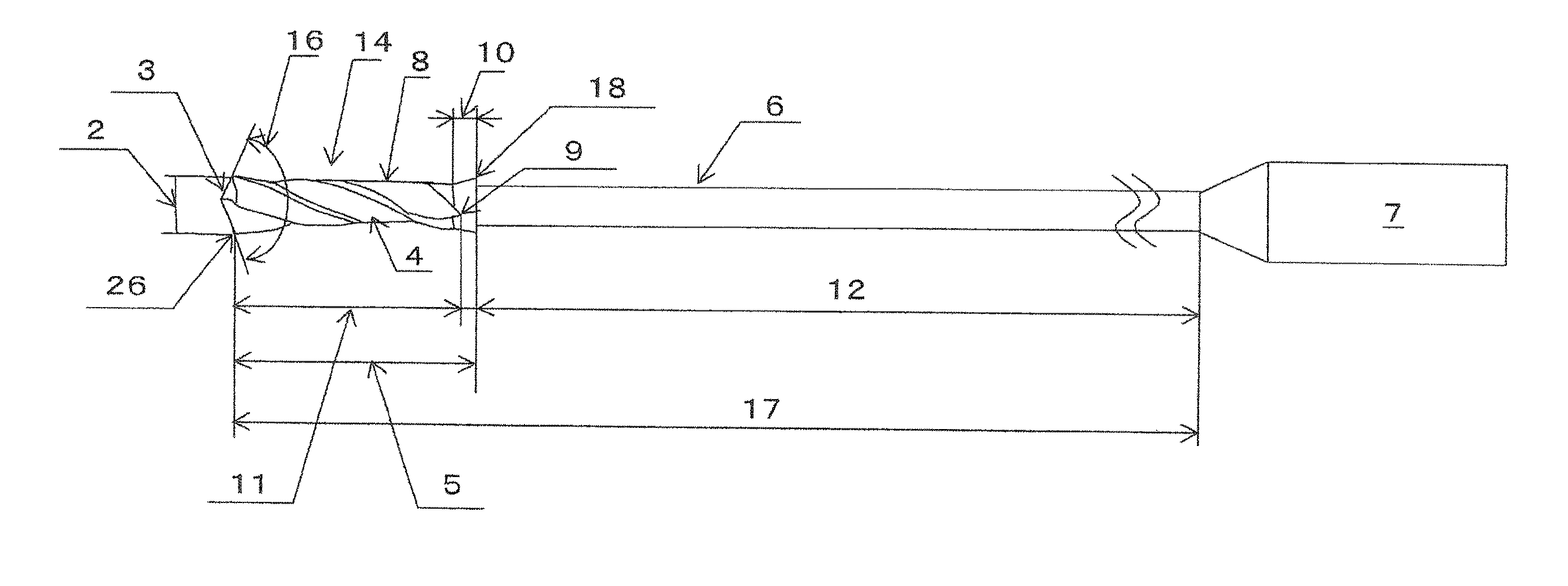
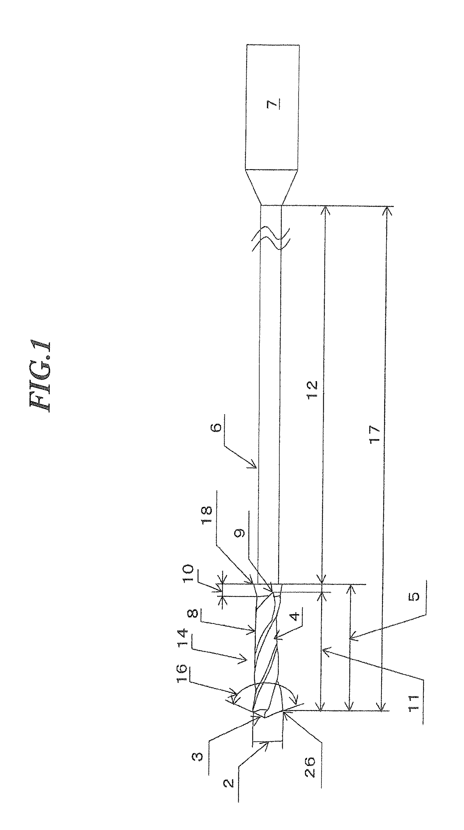
[0160]As examples of the present invention and comparative examples, each drill is provided with two cutting edges, having a drill diameter of 0.2 mm, a flute helix angle of 30 degrees, a web thickness of 0.07 mm (35% of the drill diameter), a shank diameter of 3 mm, and a drill section length 5 of 1.1 mm. Various parameters are shown in Table 1, including flute length, diameter reduction of outer diameter (back tapering amount), outer diameter at flute end, and maximum diameter of straightly tapered expanded-diameter portions. In Table 1, flute length, outer diameter at flute end, and maximum diameter of straightly tapered expanded-diameter portion are each expressed as a ratio with respect to the drill diameter. A base material for each drill is an ultra-fine-grained cemented carbide in which the average particle size of WC is 0.6 μm or less and Co content is 13 w %, with the drill section and the neck section being covered with an AlCrN coating.
[0161]As test condition, SUS304 rec...
example 2
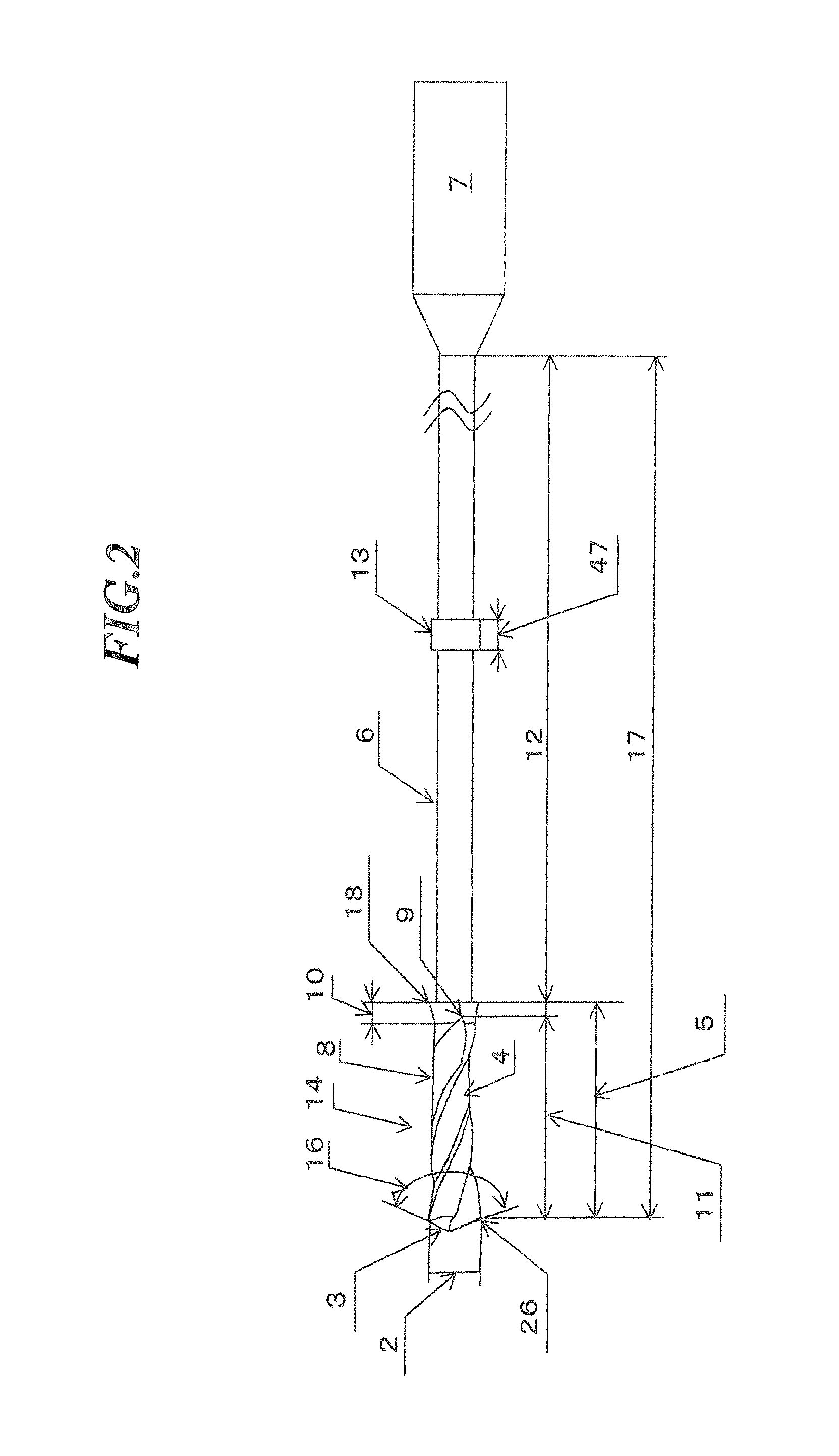
[0166]As examples of the present invention and comparative examples, each drill was provided with two cutting edges, having a drill diameter of 0.2 mm, a drill section of 1.1 mm, a neck section length of 9, 0 mm, an overall length of 40 mm, a flute helix angle of 30 degrees, a web thickness of 0.07 mm (35% of the drill diameter), a shank diameter of 3 mm, and a guide portion located 2.0 mm from the cutting edge of the neck section. Various samples were prepared having different neck section outer diameters, guide portion outer diameters, guide portion lengths, flute lengths, outer diameter reductions (back tapering amount), flute end outer diameters, and maximum diameters of the straightly tapered expanded-diameter portion, as shown in Table 1. A base material for each drill is an ultra-fine-grained cemented carbide in which the average particle size of WC was 0.6 μm or less and Co content was 13 w %, with the drill section and the neck section being covered with an AlCrN coating.
[0...
PUM
| Property | Measurement | Unit |
|---|---|---|
| diameter | aaaaa | aaaaa |
| feeding speed | aaaaa | aaaaa |
| feeding speed | aaaaa | aaaaa |
Abstract
Description
Claims
Application Information