Eureka AIR delivers breakthrough ideas for toughest innovation challenges, trusted by R&D personnel around the world.

Vibrator for bone conducting hearing devices

a bone conducting and hearing device technology, applied in the field of vibrations, can solve problems such as user discomfort, user eczema, user problems,

Active Publication Date: 2010-07-15
COCHLEAR LIMITED
View PDF52 Cites 14 Cited by
  • Summary
  • Abstract
  • Description
  • Claims
  • Application Information

AI Technical Summary

Problems solved by technology

This causes the user a feeling of pressure, discomfort, and sometimes even eczema.
In some cases it even causes the user problems like running ears due to chronic ear inflammations or infections in the auditory canal.
A disadvantage with this type of vibrator arrangement is the fact that it comprises so many small parts which makes it difficult to assemble.
Another disadvantage with the known arrangement is the fact that the vibratory isolation is not always optimal due to the fact that the outer spring, that is in the form of a small, thin metal plate which is weak in one direction, perpendicular to the plane of the spring plate, but stiff against movements in other directions parallel to the plane of the spring plate and also stiff against rotary movements.

Method used


Image

  • Vibrator for bone conducting hearing devices
  • Vibrator for bone conducting hearing devices
  • Vibrator for bone conducting hearing devices

Examples


Embodiment Construction

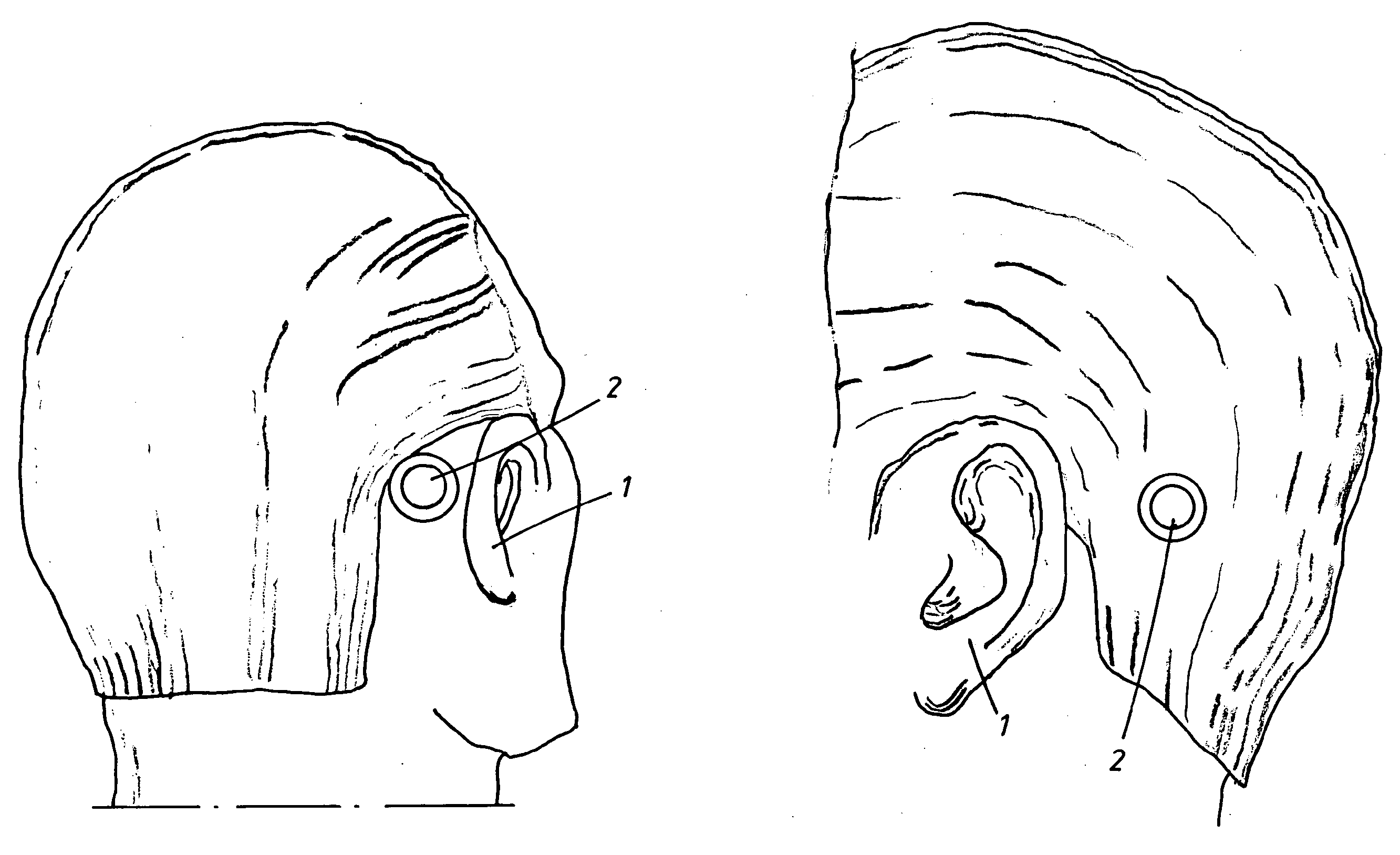
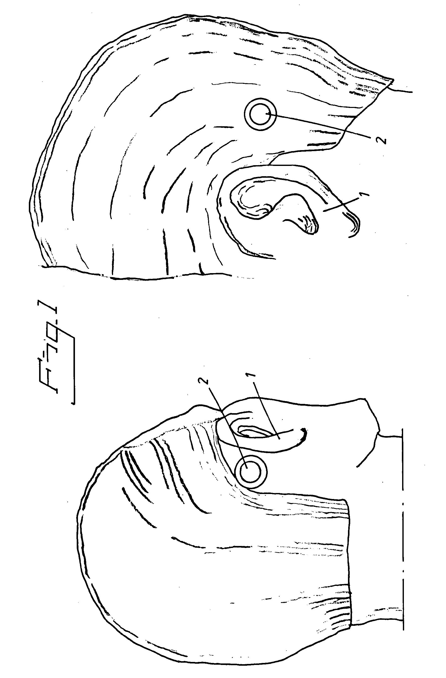
[0022]FIG. 1 shows schematically the general location of the bone conducting hearing aid device according to the invention. The hearing aid device is anchored in the skull bone, preferably in the mastoid bone, behind the external ear 1 of a person. The hearing aid device may comprise of two separate parts, an externally located part, schematically indicated by reference numeral 2 in the figure, and an implanted part. However, also the entire hearing aid device might be implanted in the mastoid bone behind the external ear 1. The sound is received by the external part 2 via a microphone and is then amplified and filtered in an external electronic circuitry which is power supplied by a battery. The amplified signal is transmitted by induction (transcutaneously) or by any other known means, such as a cord connection, through the skin to the implanted part (percutaneously). These parts are well known in the art and will not be described in any detail here.

[0023]To use inductive transmis...


PUM


Abstract

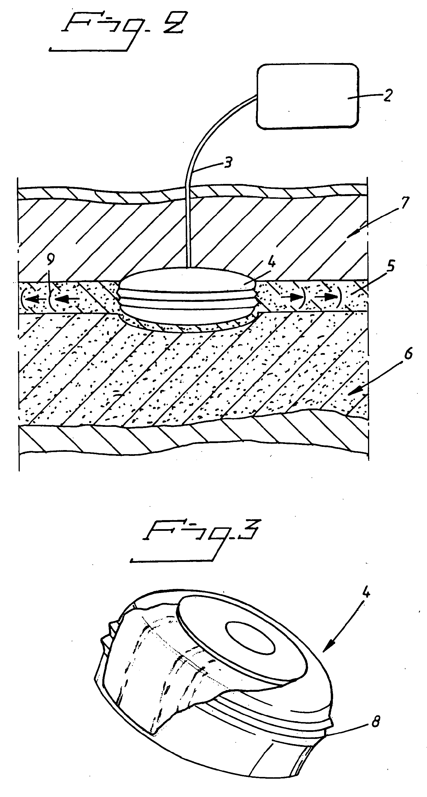
A vibrator for generating vibrations in a bone conducting hearing device, i.e. a hearing device of the type in which the sound information is mechanically transmitted via the skull bone directly to the inner ear of a person. The vibratory movements are provided by a piezo-electric or magneto-elastic element arranged to transfer the vibrations via the skull bone from the area behind the outer ear to the inner ear. The piezo-electric or magneto-elastic element is arranged to be at least partially implanted in a surgically drilled hole directly into the mastoid bone behind the outer ear so that the vibrations are transferred directly from the element to the bone and transferred in the skull bone to the inner ear. The element is encapsulated with a bone integrating material, such as titanium or various biocompatible ceramic materials or coatings and is disc shaped and acts with a radial expansion upon electrical stimulation so that longitudinal sound waves are induced into the skull bone.

Description

CROSS-REFERENCE TO RELATED APPLICATIONS[0001]This application is a national stage application under 35 USC §371 (c) of PCT Application No. PCT / SE2008 / 000336, entitled “VIBRATOR FOR BONE CONDUCTING HEARING DEVICES,” filed on May 20, 2008, which claims priority from Swedish Patent Application No. 0701242-0, filed on May 24, 2007. This application is related to commonly owned and co-pending U.S. Utility Patent Application entitled “IMPLANT ABUTMENT,” filed Nov. 24, 2009, which is a national stage application of PCT Application No. PCT / SE2008 / 000337, filed May 21, 2008. This application is also related to commonly owned and co-pending U.S. Utility Patent Application entitled “ANCHORING ELEMENT” which is a national stage application under 35 USC §371 (c) of PCT Application No. PCT / SE2008 / 000338, filed on May 21, 2008. The entire disclosure and contents of the above applications are hereby incorporated by reference herein.BACKGROUND[0002]1. Field of the Invention[0003]The present inventio...

Claims


Application Information

Patent Timeline
Patent Type & Authority Applications(United States)
IPC IPC(8): H04R25/00
CPCH04R17/00H04R2460/13H04R25/606
Inventor ANDERSSON, MARCUSHOLGERSSON, ERIKJINTON, LARSSTROMSTEN, PATRICK
Owner COCHLEAR LIMITED
Why Eureka
Eureka Blog
Learn More