Method for Forming Functional Spectral Filter

a functional spectral filter and filter technology, applied in the field of functional spectral filtering, can solve the problems of color deficient observers, difficult to differentiate, and difficult for protanopes and deuteranopes to sense a difference between the colors in a combination of red and green

Active Publication Date: 2010-07-15
TOYOHASHI UNIVERSITY OF TECHNOLOGY +1
View PDF4 Cites 11 Cited by
  • Summary
  • Abstract
  • Description
  • Claims
  • Application Information

AI Technical Summary

Benefits of technology

[0021]An object of the present invention is to provide a method for forming a functional spectral filter having a novel structure in which it is possible to vary color sensitivity of a light receiving member into a desired pattern via the filter, and it is possible to solve the above-described various problems, and which can be applied to a wide range of usages.

Problems solved by technology

Color deficient observers are color deficient due to any of three cone photoreceptor cells existing in color normal observers being abnormal or defective.
Because the protanopes and the deuteranopes have similar sensitivity curves in the red cone photoreceptor cell and green cone photoreceptor cell, color appearances and color combinations (combination colors) difficult to differentiate between them are very similar.
It has been described that it is difficult for the protanopes and the deuteranopes to sense a difference between the colors in a combination of red and green.
However, even if it is easy for a color normal observer to recognize information because it is easy to distinguish colors in its color scheme, it is difficult for a color deficient observer to distinguish the colors in the color scheme, and therefore, it is difficult to recognize the information, which leads to a barrier (interference) of information recognition in many cases.
As such, any of these methods controls only the transmittance in a wavelength band with the maximum sensitivity of the three types of cone photoreceptor cells, but does not control the entire visible light wavelength band.
Therefore, those methods have a certain effect on a color combination in which it is difficult for a color deficient observer to distinguish its colors.
However, because the control for a transparent wavelength band is imperfect, it is difficult to achieve an effect on other color combinations in some cases.
Further, in these methods, a transmitted light is colored, and for example, it appears reddish overall in some cases.
As a result, in many cases, an observer has a sense of discomfort, and feels fatigued in his / her daily life.
However, in the present situation, the response to a universal design (barrier-free) for color deficient observers is much less advanced than the response to other disabled.
It has been described that a major cause thereof is that it is difficult for color normal observers to intuitively understand the inconveniences which color deficient observers sense.
However, in such an image processing method by software, for notices / facilities / public indications which are already installed, industrial products, and the like, because it is necessary to once input image data into a data processing device, and to scan and detect it, there are many working processes, which makes it difficult to import the method into an everyday workflow.
Further, because it is necessary for such an image processing method by software to depend on a method for observing an image on a computer display, resultingly, an entire visual field does not approach to a color world which a color deficient observer senses, and it can only be said that the method is insufficient for an actual sensation of inconveniences.
As a greater problem, there is the problem that it is necessary to determine an object in advance, and to take a photograph thereof, and the like, which is inconsistent with real-time performance, and this is far from physically sensing inconveniences in one's daily life.

Method used


Image

  • Method for Forming Functional Spectral Filter
  • Method for Forming Functional Spectral Filter
  • Method for Forming Functional Spectral Filter

Examples


example 1

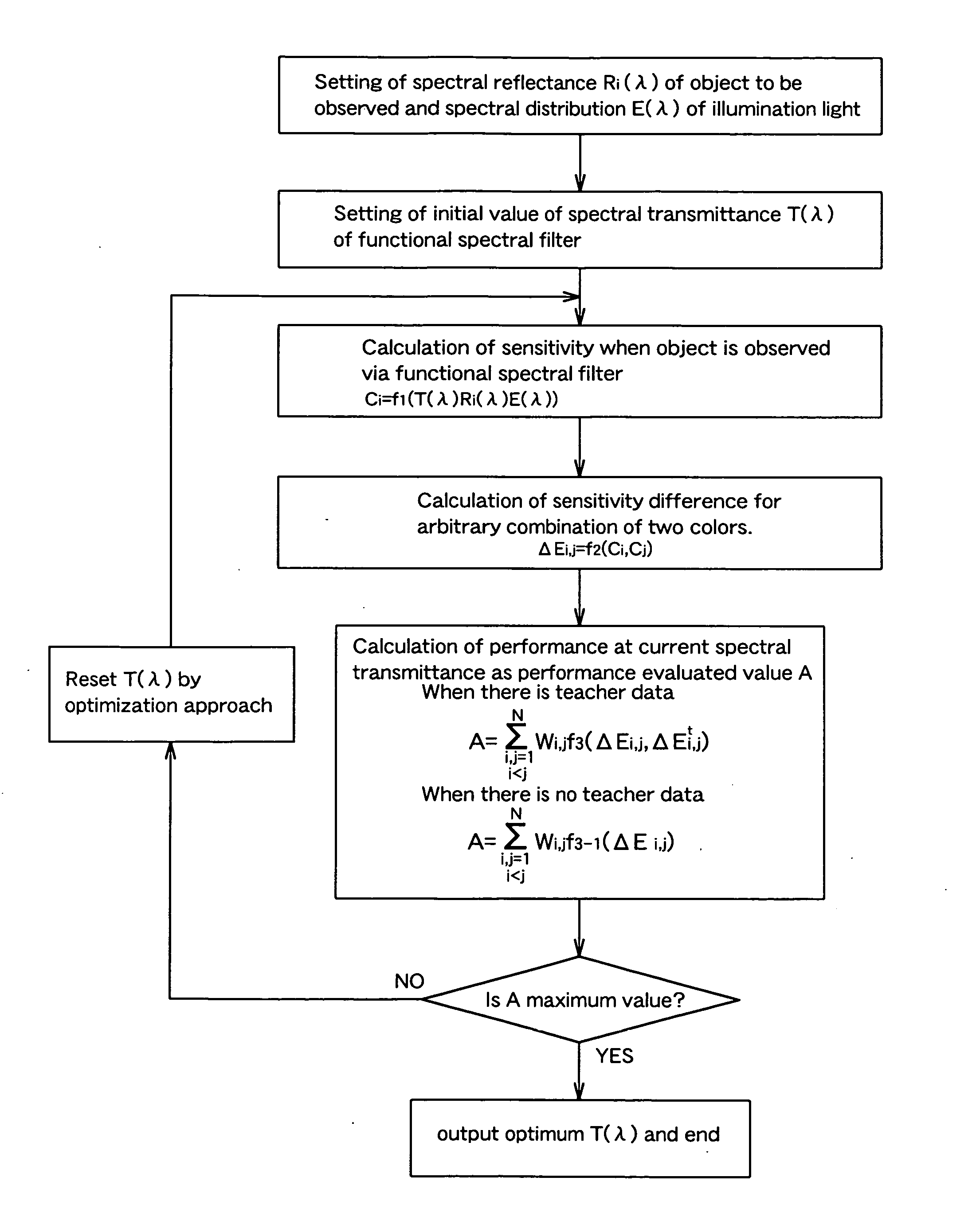
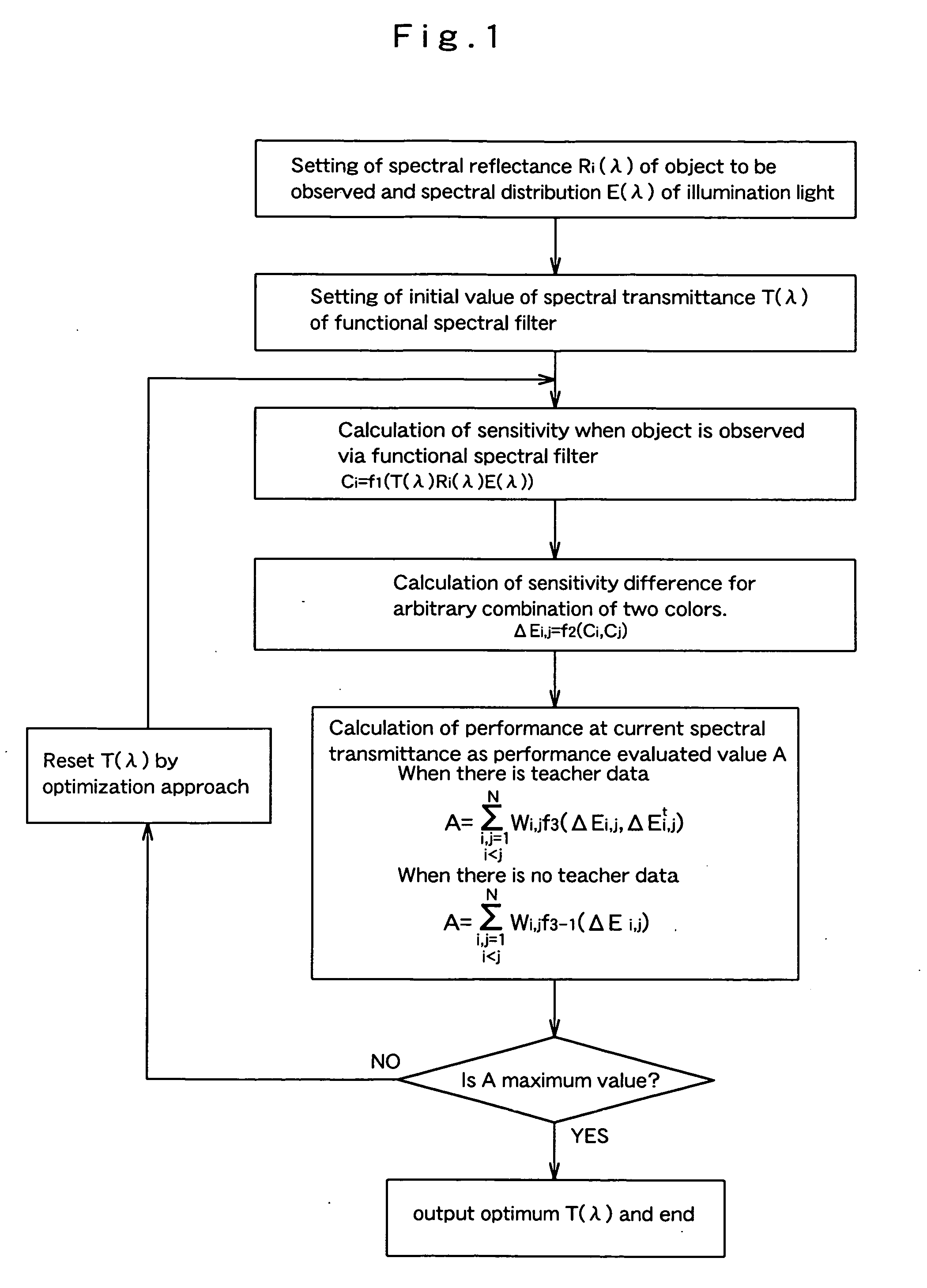
[0148]The present example relates to a method for forming a filter through which it is possible to understand inconveniences in distinguishing colors for a color deficient observer, but also which can be introduced in a workflow in a practical work.

[0149]16 colors in a D-15 color rendering-index (N=16) commonly used for color vision tests have been regarded as colors of an object to be observed (specified colors, i.e., an object color group), and a D-65 serving as a standard light source has been used as an illumination light.

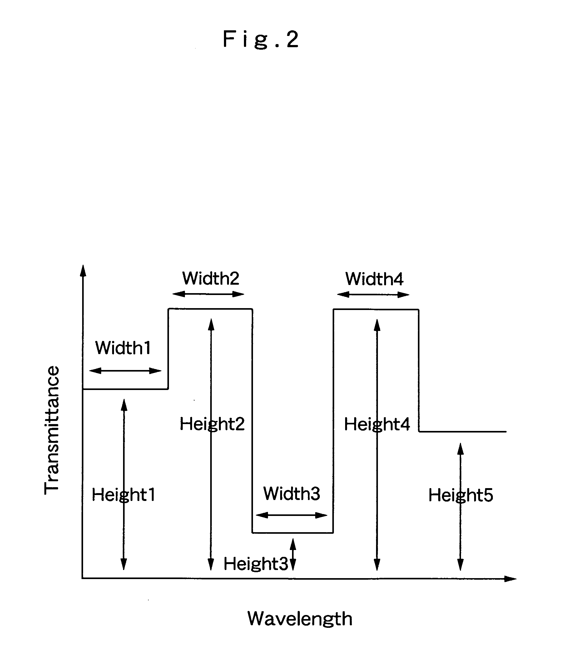
[0150]A visible light wavelength band (λ=380 to 780 nm) is divided into five intervals as shown in FIG. 2, and by use of a step function consisting of nine parameters (of widths: 4+heights: 5) which are composed of the respective wavelength intervals (widths) and the transmittances (heights) corresponding to the respective wavelength intervals, a spectral filter model is described as T(λ)=T(p1, p2, . . . , p9). These parameter values are limited within a range ...

example 2

[0175]The present example relates to a method for forming a functional spectral filter through which it is possible to make it easy to distinguish specified colors by the color deficient observer wearing the filter.

[0176]In the same way as in the example 1, 16 colors in a D-15 color rendering-index (N=16) have been regarded as colors of an object to be observed (i.e., an object color group), and by using a D-65 serving as a standard light source, a color difference ΔEDi,j of a color deficient observer has been determined by use of a spline function model with the number of parameters 16.

[0177]Note that the spline function model used as a spectral transmittance model for the spectral filter is represented by the following formula 17.

[Formula17]T(λ)=∑k=116pkBk(λ),whereBk(λ)={{ω3+3ω2(ω-λ-λk)+3ω(ω-λ-λk)2-3(ω-λ-λk)3} / 6ω3:whenλ-λk≤ω(2ω-λ-λk)3 / 6ω3:whenω≤λ-λk≤2ω0:when2ω≤λ-λk}

[0178]Here, a visible light wavelength band 380 to 780 nm is an analysis object, λk is set so as to range from 350 to...

example 3

[0188]The present example relates to a method for forming a spectral filter through which a difference in a specific color group is enhanced.

[0189]As a concrete example for designing a functional spectral filter through which a color difference with respect to a color combination specified in advance is made large or made small, a spectral filter to distinguish between greens of leaves of natural plants and greens of artificial leaves is prepared.

[0190]First, given that greens of leaves of natural plants have been set as an A group, greens of artificial leaves have been set as a B group, and a total of six colors of three colors randomly selected respectively from the A group and the B group have been regarded as colors of an object to be observed (that is, an object color group), a spline function model with the number of parameters 23 is used by use of the spectral distributions of the respective reflected lights.

[0191]Because the present example is a case in which there is no tea...


PUM


Abstract

To provide a functional spectral filter through which, it is possible for an observer wearing the functional spectral filter to change his or her color sensitivity (ease of color distinction), and which is for designing a color scheme easy to be distinguished for a color deficient observer by using the filter. A functional spectral filter including a multilayer is formed in accordance with a thin film design (an optimization method) determined by use of a color vision theory so as to make color sensitivity into a desired pattern. With respect to combinations that two colors among a plurality of specified colors are combined, color differences in the respective combinations are made close to a color difference given in advance. Alternatively, with respect to specified combinations, the color differences are made small or the color differences are made large.

Description

TECHNICAL FIELD[0001]The present invention relates to a method for forming a functional spectral filter. In particular, the present invention relates to a method for forming a transmission type functional spectral filter, which is suitable as a tool to correct color vision of a color deficient observer, and reversely, to allow a color normal observer to experience the inconveniences of a color deficient observer, so as to deepen understanding about the color deficient observer.[0002]Here, a case of a transmission type functional spectral filter will be mainly described as an example. However, a case of a reflection type (mirror type) functional spectral filter is equally applicable.[0003]The term “tool” here means, for example, filters disposed in front of or inside imaging devices such as cameras, photodiodes, and monochrome cameras, filters disposed in front of or inside optical systems such as televisions, monitors, and various light sources, and spectacle lenses, contact lenses,...

Claims


Application Information

Patent Timeline
Patent Type & Authority Applications(United States)
IPC IPC(8): G06F17/10
CPCG02B5/285G01J2003/466
Inventor NAKAUCHI, SHIGEKIONOUCHI, TATSUYAKATOU, HIROHISAODA, HIROFUMISAITOU, YUUJIMIYAZAWA, KANAE
Owner TOYOHASHI UNIVERSITY OF TECHNOLOGY
Why Eureka
Try Eureka