Unmanned helicopter

a helicopter and helicopter body technology, applied in the field of unmanned helicopters, can solve the problems of front surface, reduced cooling performance, and downwashing, and achieve the effects of improving cooling performance, improving cooling performance, and large area

Inactive Publication Date: 2010-07-22
YAMAHA MOTOR CO LTD
View PDF2 Cites 31 Cited by
  • Summary
  • Abstract
  • Description
  • Claims
  • Application Information

AI Technical Summary

Benefits of technology

[0013]According to the present invention, as the radiator can be formed in a large size outside the main body, it is possible to provide a wind receiving part of the radiator with a large area so that cooling performance may be improved. As the wind reception surfaces of the radiator are oriented in the longitudinal direction of the airframe, a wind is sufficiently received during a forward movement. As the lateral end of the radiator in the width direction projects outward beyond the lateral edge of the bottom surface of the main body, a wind is sufficiently received during a backward movement. The downwash generated by the rotation of the main rotor flows downward and in the direction of the rotation of the main rotor. Accordingly, the downwash blows on the lateral end of the radiator from the obliquely upward direction. Consequently, the radiator can receive a wind caused by the downwash during hovering.
[0014]Therefore, the unmanned helicopter provided with the radiator according to the present invention not only improves cooling performance during a forward movement but also improves cooling performance during a backward movement or hovering, which prevents the radiator from receiving a wind from the forward direction. Further, as the radiator is positioned inward in the width direction of the airframe within the skid, the unmanned helicopter is easily handled when transported on the ground or carried by a load carrier of a transportation vehicle. Still further, the space occupied by the airframe of the unmanned helicopter according to the present invention is not enlarged by the radiator, and the airframe is compact. As a result, the space necessary for transportation or parking may be small.

Problems solved by technology

When the airframe moves forward, the front surface of the radiator receives a wind caused by the flight and also receives a downwash from the main rotor.
In this case, as the radiator cannot receive a wind on the front during a backward movement, cooling performance decreases.
Therefore, a flight such as hovering or a backward movement at a very slow speed is rarely performed.
If a long flight is performed in such a condition, the wind caused by the flight is not easily received by the front of the airframe.
As a result, while such a flight is performed, it is not possible to sufficiently cool the engine.

Method used


Image

  • Unmanned helicopter
  • Unmanned helicopter
  • Unmanned helicopter

Examples


first embodiment

[0024]An embodiment of the unmanned helicopter according to the present invention will be described hereinafter in detail with reference to FIGS. 1 to 5.

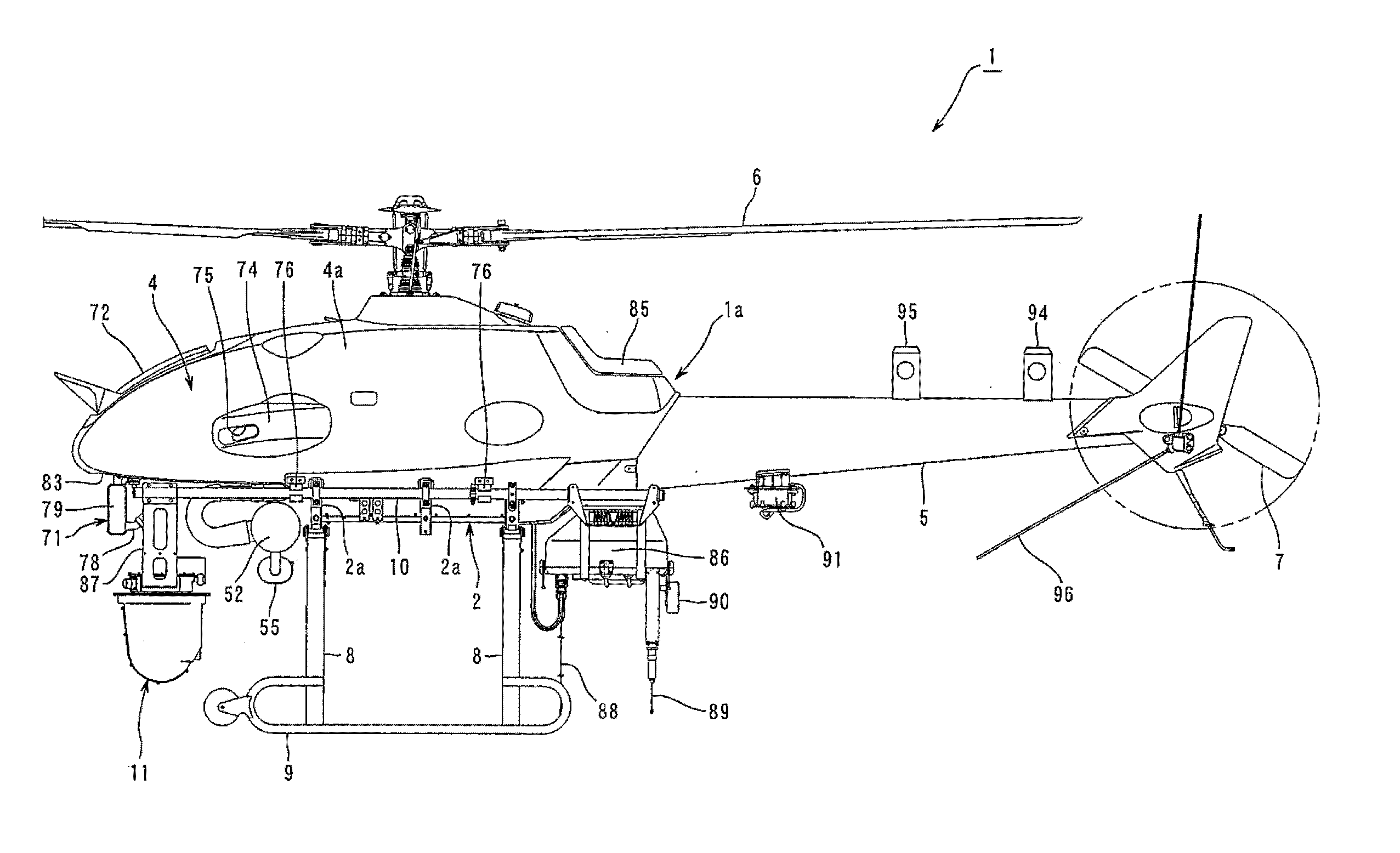
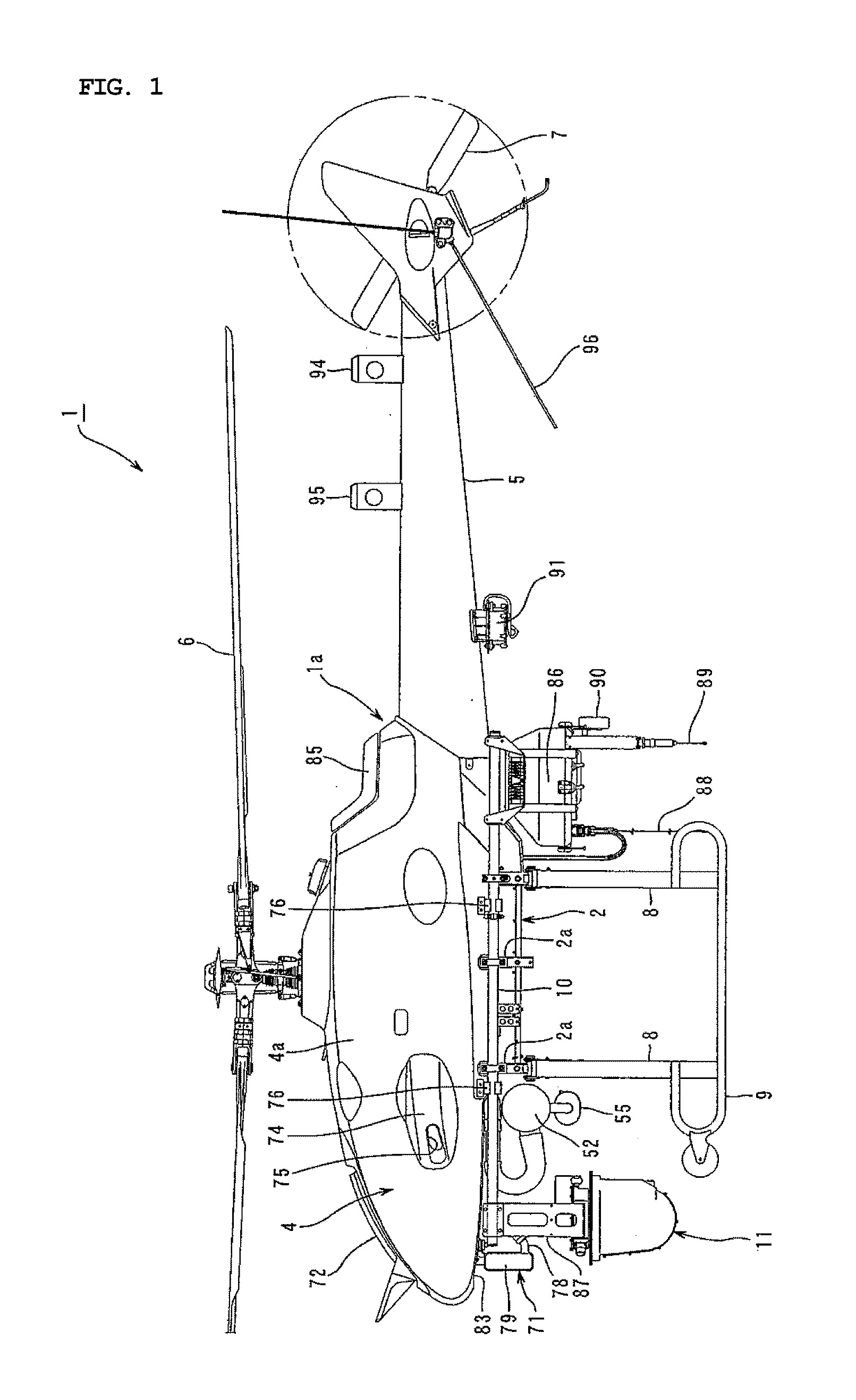
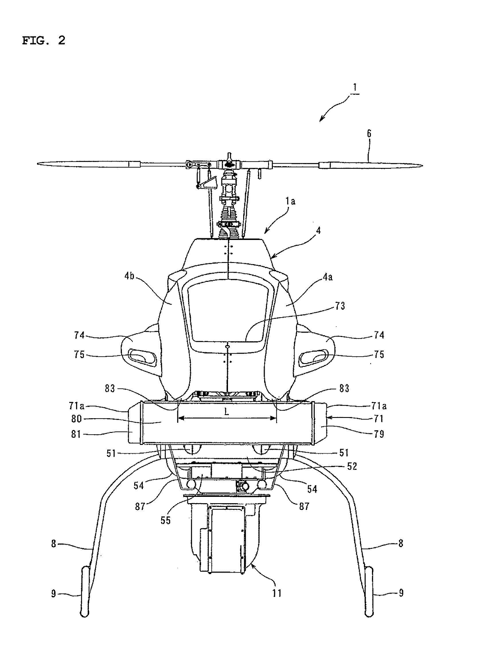
[0025]An unmanned helicopter 1 according to the embodiment has an airframe 1a including a body frame 2 described below (see FIG. 4 and FIG. 5), a power unit 3 mounted on the body frame 2, a main body 4 covering the outer circumference of the body frame 2 except the bottom area (see FIG. 1 to FIG. 3), and a tail body 5 connected to the rear end of the body frame 2. A main rotor 6 is provided on the upper part of the main body 4, and a tail rotor 7 is provided to the rear part of the tail body 5.

[0026]As shown in FIG. 4 and FIG. 5, the body frame 2 is formed in a shape of a hollow box extended in the longitudinal direction of the unmanned helicopter 1. A couple of support legs 8 disposed in the longitudinal direction of the airframe 1a is fixed on the lower end of the body frame 2. The support legs 8 are formed extendedly downward fro...

second embodiment

[0066]The unmanned helicopter according to the present invention can be constituted as shown in FIG. 6 to FIG. 8. In these drawings, a member equal to or equivalent to a member already described with reference to FIG. 1 to FIG. 5 is given the same reference numeral or symbol, and a detailed description thereof will not be repeated in an appropriate manner.

[0067]In the helicopter 1 according to the embodiment, the second radiator 71 formed in a horizontal long shape which is longer in the vertical direction is provided in a position below the main body 4 at the left side of the airframe 1a. The second radiator 71 shown in the second embodiment constitutes the radiator described in Claim 3 of the present invention. As shown in FIG. 7 and FIG. 8, the second radiator 71 according to the embodiment is attached to the payload bar 10 positioned at the left side of the airframe by a bracket 10a.

[0068]Specifically, as shown in FIG. 6, the second radiator 71 according to the embodiment is po...


PUM


Abstract

An airframe (1a) having a main body (4) and a tail body, a main rotor (6) disposed above the main body (4) and driven by an engine inside the airframe (1a), and a tail rotor disposed in a rear part of the tail body (5) are provided. A pair of support legs (8, 8) at left and right sides extending downward from left and right sides in a lower part of the main body (4) and a pair of skids (9) on left and right sides provided on the lower ends of the support legs (8) and positioned out of the main body (4) in the width direction of the airframe (1a) in a front view are provided. A radiator (71) at a position more frontward than the front ends of the skids (9) in a side view, formed extendedly downward from the vicinity of a bottom surface (83) of the front part of the main body, and having wind reception surfaces oriented to the longitudinal direction of the airframe is provided. Lateral ends of the radiator (71) in the width direction of the airframe (1a) project outward beyond lateral edges of a main body bottom surface (83) in the vicinity of the radiator (71) in a front view. Further, the lateral ends (71a) of the radiator (71) are positioned inward in the width direction of the airframe (1a) within skids 9.

Description

TECHNICAL FIELD[0001]The present invention relates to an unmanned helicopter having a radiator.BACKGROUND ART[0002]Conventionally, an unmanned helicopter which is controlled by remote control performed by an operator watching an airframe is used for applying agrochemicals or for photographing aerial images, videos, and the like from the sky. An unmanned helicopter in recent years can fly out of the operator's sight by utilizing the GPS. As a result, an unmanned helicopter of this type can photograph images of a place such as, for example, a volcano and a disaster site to which it is difficult for a manned helicopter to go closer and, actually, plays an active part in such a place. For example, an unmanned helicopter for applying chemicals such as agrochemicals is disclosed in JP-A-2002-166893, while an unmanned helicopter for photographing aerial images and the like is disclosed in JP-A-2002-293298.[0003]A conventional unmanned helicopter is provided with a radiator oriented to an o...

Claims


Application Information

Patent Timeline
Patent Type & Authority Applications(United States)
IPC IPC(8): B64C27/06B64D33/10B64C27/04
CPCB64C39/024B64C2201/024B64C2201/127B64C2201/108B64C2201/044B64U50/11B64U30/20B64U2101/30B64U10/10B64C27/06A01M7/00A01C7/08
Inventor SAKAMOTO, OSAMUHIRAMI, IKUHIKONAKAYAMA, HIRONORI
Owner YAMAHA MOTOR CO LTD
Why Eureka
Try Eureka