Engine mounting structure for aircraft having a beam spreader connected at four points

a technology of beam spreader and mounting structure, which is applied in the direction of power plant arrangement/mounting, aircraft power plant construction, power plant structure, etc., can solve the problems of appreciably penalising overall mass, high encumbrance, and costly assembly and disassembly times, so as to achieve advantageous reduction of overall mass and encumbrance of thrust effort transmission devi

Inactive Publication Date: 2010-07-22
AIRBUS OPERATIONS (SAS)
View PDF27 Cites 35 Cited by
  • Summary
  • Abstract
  • Description
  • Claims
  • Application Information

AI Technical Summary

Benefits of technology

[0019]Thus, in normal thrust efforts transmission mode, the efforts transit in a traditional manner successively through the lateral connecting rods, the lateral ends of the spreader beam, the spreader beam's connecting device, and finally the support element which is fixed relative to the rigid structure. Due to the play allowed for the link incorporating the secondary spreader beam connecting device, this link remains inoperative in the transmission of the efforts for as long as the normal transmission mode continues, i.e. for as long as the thrust efforts transmission device is not subject to failure. This also enables an isostatic unit to be retained in normal mode.
[0021]Consequently, despite the failure of one of the lateral connecting rods, the spreader beam remains connected at three points, forming for example a V-shape, the point of which is constituted by the principal spreader beam connecting device. It must be understood that the further the secondary spreader beam connecting device is from the principal spreader beam connecting device, the greater the observed leverage, and therefore the less high are the efforts transiting through the principal connecting device. This advantageously enables a reasonable dimensioning for the primary and secondary connecting devices, and also for their surrounding elements, which are non-penalising in terms of mass and encumbrance.
[0023]Above all, the rear ends of the lateral connecting rods no longer require the incorporation of an additional link in order to respond to a possible fracture of the linking device with the associated lateral end of the spreader beam, since in the latter case the efforts are transmitted in the original manner described above, specific to the present invention. Thus, the design of the whole of the rear part of the engine mounting system is able to be simplified.
[0026]Moreover, in the event of a failure taking the form of a fracture of the principal spreader beam connecting device, the standby link incorporating the secondary spreader beam connecting device becomes active, through the fact that parts initially assembled with some play between them come into contact. Consequently, despite the failure of this principal device, the spreader beam remains connected at three points, preferably forming a V-shape, the point of which is constituted by the secondary spreader beam connecting device, and the two ends of which remain connected to the lateral connecting rods. Due to the location of the secondary hinge line in plane (P), the efforts transiting through the two lateral connecting rods can advantageously be balanced in identical or similar fashion to that found in normal mode, using the principal connecting device.
[0027]It is no longer necessary to have a twin connecting device, since a single device is indeed sufficient, due to the existence of the safety force pathway specific to the present invention. The overall mass and the encumbrance of the thrust efforts transmission device are advantageously reduced thereby.

Problems solved by technology

These configurations not only imply a complex design of the rear part of the engine mounting system, which leads to substantial and consequently costly assembly and disassembly times, but also lead to high encumbrance, and also an appreciably penalising overall mass.
It has the disadvantage of requiring a substantial encumbrance, notably in relation to its spreader beam, the lateral ends of which must be over-dimensioned in order to be brought as close as possible to their respective stops on the rear engine attachment strut.
Both the technical solutions presented above, enabling a response to be found to the fracture of one of the lateral thrust efforts transmission connecting rods, also have a joint disadvantage in the combination of a substantial number of separate force pathways which must find their way through the rear part of the engine mounting system, making its design quite complicated and bulky.

Method used


Image

  • Engine mounting structure for aircraft having a beam spreader connected at four points
  • Engine mounting structure for aircraft having a beam spreader connected at four points
  • Engine mounting structure for aircraft having a beam spreader connected at four points

Examples


Embodiment Construction

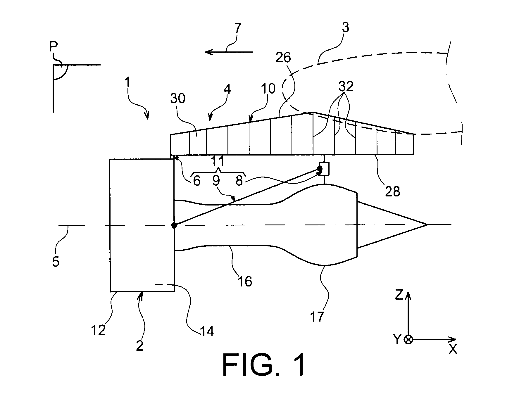
[0047]With reference to FIG. 1, it shows an engine unit 1 for aircraft intended to be attached under a wing 3 of this aircraft, where this unit 1 forming the subject of the present invention is fitted with an engine mounting structure 4 taking the form of a preferred embodiment of the present invention.

[0048]Overall, engine unit 1 comprises an engine such as a jet engine 2 and engine mounting structure 4, where the latter is notably fitted with a rigid structure 10 and an engine mounting system 11 comprising multiple engine attachments 6, 8, and a system for transmission of thrust efforts 9 generated by jet engine 2, where mounting system 11 is therefore interposed between the engine and the abovementioned rigid structure 10; the latter is also called the primary structure. As an indication, it should be noted that unit 1 is intended to be surrounded by a nacelle (not represented), and that engine mounting structure 4 comprises another series of attachments (not represented) enablin...


PUM


Abstract

An engine mounting structure for aircraft including an engine mounting system including a device for transmission of the thrust efforts fitted with two lateral connecting rods and with a spreader beam mounted in connected fashion on a support element, through a principal connecting device defining a principal spreader beam hinge line positioned in a plane. The spreader beam is also mounted in connected fashion with some play on the element, using a secondary connecting device located at some distance, as seen from above, from the device, and defining a secondary spreader beam hinge line, which is also positioned in a plane. The rotation of the spreader beam is stopped by device coming into contact with the spreader beam.

Description

TECHNICAL FIELD[0001]The present invention relates generally to an engine unit for an aircraft, of the type comprising an engine, an engine mounting structure, and an engine mounting system with multiple engine fasteners, which is interposed between a rigid structure of the engine mounting structure and the engine.[0002]The invention also relates to such an aircraft engine mounting structure.[0003]The invention may be used in any type of aircraft fitted, for example, with jet engines or turboprop engines.[0004]This type of engine mounting structure, also called an “EMS”, allows, for example, a turboshaft engine to be suspended beneath the wing surface of the aircraft, or indeed allows this turboshaft engine to be mounted above this same wing surface.STATE OF THE PRIOR ART[0005]Such an engine mounting structure is, indeed, designed to constitute the linking interface between an engine such as a jet engine and a wing surface of the aircraft. It enables the efforts generated by its jet...

Claims


Application Information

Patent Timeline
Patent Type & Authority Applications(United States)
IPC IPC(8): B64D27/26
CPCB64D2027/268B64D27/26
Inventor HARAMBURU, ERICSAMMITO, LAURENTLARROCHELLE, JEAN
Owner AIRBUS OPERATIONS (SAS)
Why Eureka
Try Eureka