Voltage regulated permanent magnet generator

a permanent magnet generator, voltage regulation technology, applied in the direction of generator control by field variation, windings, electric generator control, etc., can solve the problems of increasing the cost of the generator, increasing the maintenance necessary, and damaged components

Active Publication Date: 2010-07-22
HAMILTON SUNDSTRAND CORP
View PDF18 Cites 11 Cited by
  • Summary
  • Abstract
  • Description
  • Claims
  • Application Information

AI Technical Summary

Problems solved by technology

An aircraft electrical system will also typically have components that will be damaged unless voltages are maintained within a certain range.
Each of these methods is complex and difficult to assemble, thereby increasing the cost of the generator as well as increasing the necessary maintenance.

Method used


Image

  • Voltage regulated permanent magnet generator
  • Voltage regulated permanent magnet generator
  • Voltage regulated permanent magnet generator

Examples


Embodiment Construction

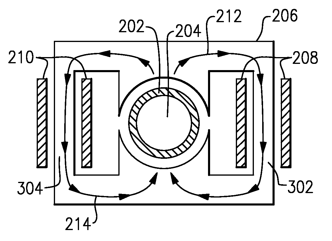
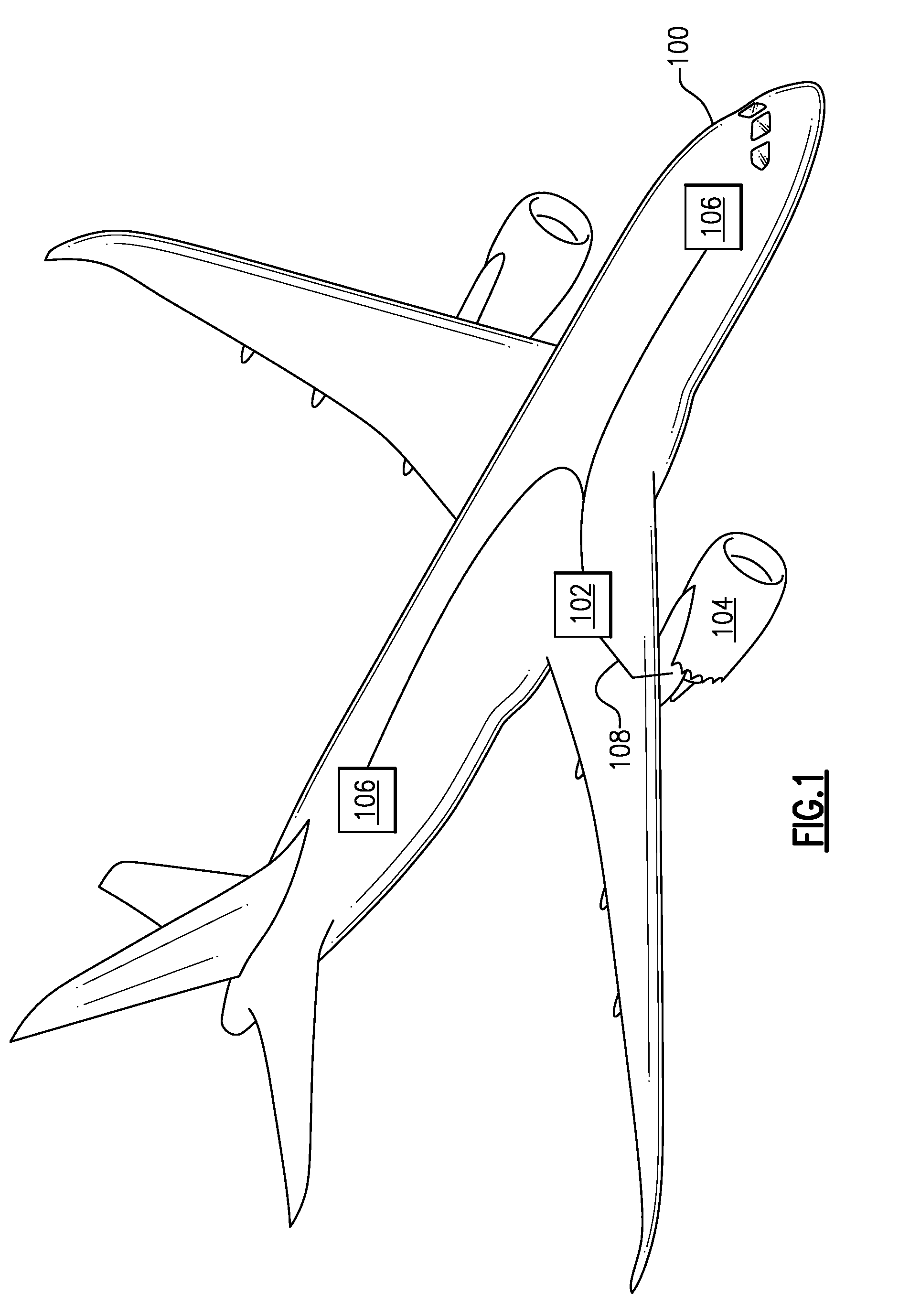
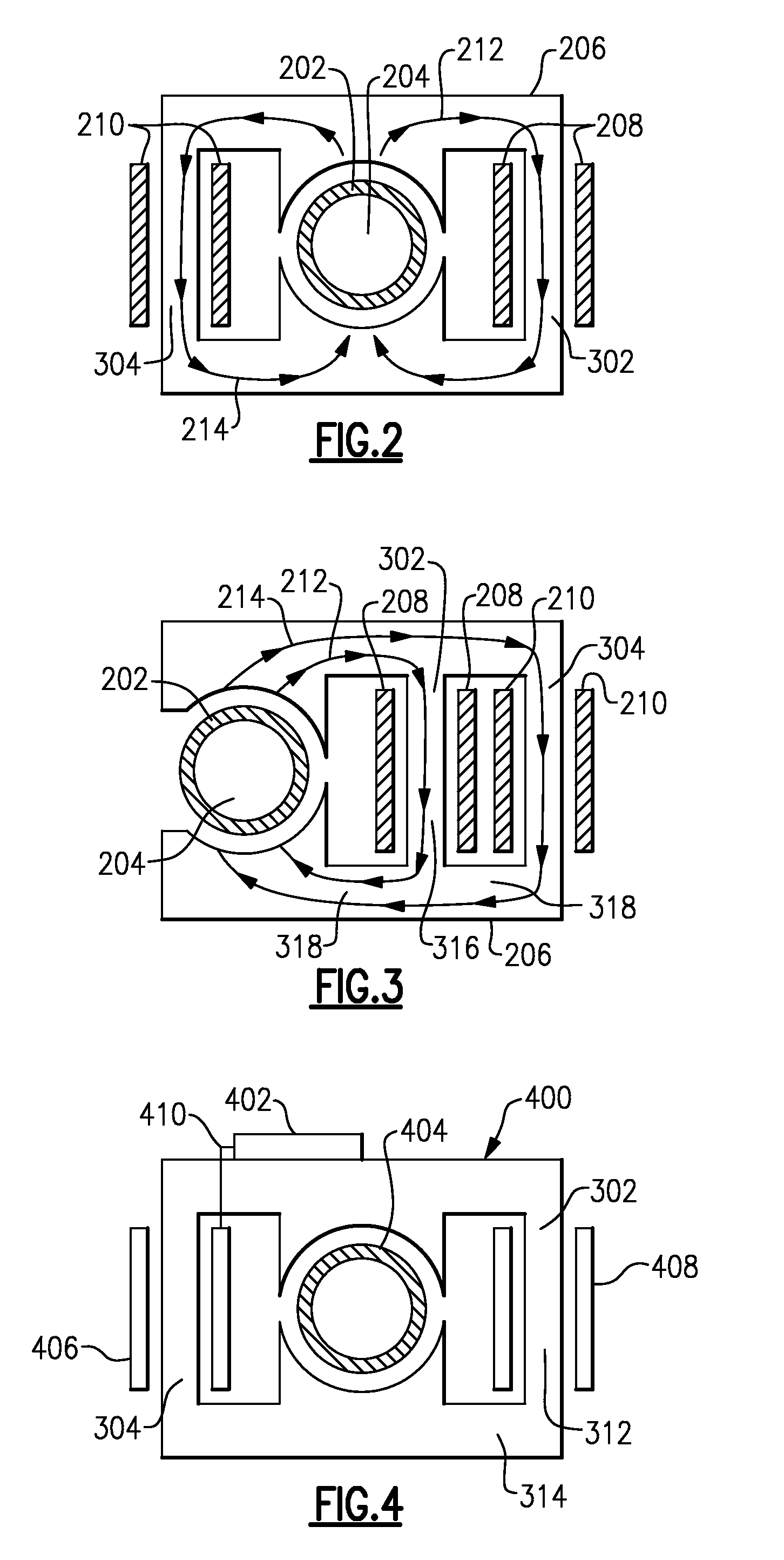
[0015]FIG. 1 illustrates an aircraft 100 that utilizes turbine engines 104 to generate thrust. The turbine engines 104 contain a mechanical connection to a single phase generator 102, shown schematically in FIGS. 2-4, which transfers rotational power from a turbine in the turbine engine 104 to a rotor within the single phase generator 102. The mechanical connection allows the rotor to turn at the same speed as the turbine engine 104 or at a speed proportional to the speed of the turbine engine 104, depending on the mechanical connection. The rotation of the rotor generates a magnetic flux which travels through a stator in the single phase generator 102. The magnetic flux passes by an armature winding, thereby causing an electrical current in the armature winding. The armature winding is connected to the aircraft electrical system, and outputs an electrical current to the rest of the system. Electric current produced by the armature winding is passed to other electronic systems 106 w...


PUM


Abstract

A single phase AC generator uses a rotor contained within a stator. The stator has an armature winding and a control winding which is capable of having its magnetic permeability adjusted, thereby limiting the output voltage of the armature winding. The stator additionally has two core sections.

Description

BACKGROUND OF THE INVENTION[0001]The present disclosure is directed toward a single phase alternating current (AC) permanent magnet generator having voltage regulation.[0002]Vehicles, such as aircraft, typically employ multiple components which require electrical power to operate. Modern aircraft also contain generators which are capable of utilizing rotational energy from an aircraft turbine engine to turn a rotor and generate electricity. The rotor speed of the generator is a function of the turbine speed of the turbine engine and cannot be adjusted without adjusting the speed of the turbine engine. An aircraft electrical system will also typically have components that will be damaged unless voltages are maintained within a certain range. In order to meet the voltage limits of the electrical system, most aircraft have utilized voltage regulated generators to generate onboard power that does not exceed the voltage limits.[0003]Voltage regulated generators used in the art typically ...

Claims


Application Information

Patent Timeline
Patent Type & Authority Applications(United States)
IPC IPC(8): H02P9/00
CPCH02K21/046
Inventor GIERAS, JACEK F.ROZMAN, GREGORY I.
Owner HAMILTON SUNDSTRAND CORP
Why Eureka
Try Eureka