Micro relay

a micro-relay and relay technology, applied in the field of micro-relay, can solve the problems of difficult to obtain sufficient ampere turns, and achieve the effect of reducing the leakage of high-frequency signals

Inactive Publication Date: 2010-07-22
MATSUSHITA ELECTRIC WORKS LTD
View PDF8 Cites 25 Cited by
  • Summary
  • Abstract
  • Description
  • Claims
  • Application Information

AI Technical Summary

Benefits of technology

[0019]In an embodiment, a first end of the core is joined to the base of the armature so that the tip of the armature can move in and out of contact with the stationary contact by elastic deformation of the armature. The magnetic member further includes a first yoke and a second yoke. The first yoke is located in a second though hole of the main substrate so that a first end of the first yoke faces the armature. The second yoke is located on the other side of the main substrate. A first end and a second end of the second yoke are joined to a second end of the core and a second end of the first yoke, respectively. The second yoke is divided into two parts by the permanent magnet between the first end and the second end of the second yoke, and the divided faces of the second yoke are joined to both magnetic pole faces of the permanent magnet with the adhesive, respectively. In this embodiment, the permanent magnet can be easily stuck between the two parts of the second yoke.
[0020]In an embodiment, the micro relay further has a gap between the part of the second end side of the second yoke and the permanent magnet. The part of the first end side of the second yoke functions as one terminal which is electrically connected to the core and the armature. For example, in the structure that the first yoke is arranged between the core and the stationary contact, even if a high frequency signal is supplied to the terminal and the stationary contact, it is possible to reduce leakage of the high frequency signal to the stationary contact via the first yoke and the armature.
[0021]In an embodiment, the cover comprises a second substrate, a magnetic member and a coil. The second substrate is located above the one side of the main substrate. The magnetic member of the cover includes a core which is arranged opposite the core of the main substrate and supported by the second substrate. The coil of the cover is used to generate a magnetic field which separates the part of the armature from the stationary contact, and is wound around the core supported by the second substrate. In this embodiment, sticking of the part of the armature to the stationary contact can be avoided.

Problems solved by technology

However, the coil of the latching relay is a planer coil, and accordingly it is difficult to obtain sufficient ampere turns.

Method used


Image

  • Micro relay
  • Micro relay
  • Micro relay

Examples


first embodiment

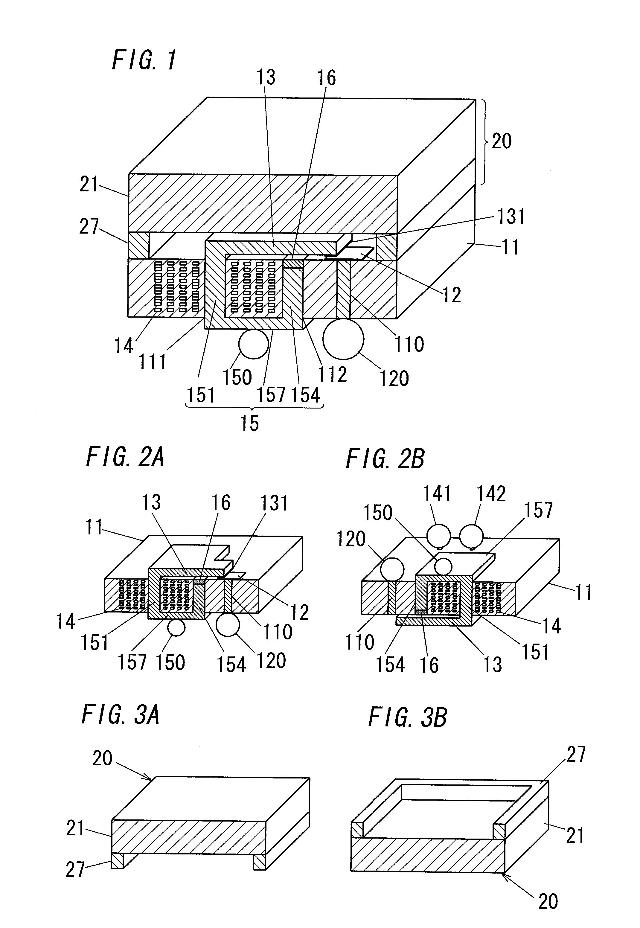
[0039]FIG. 1 shows a micro relay in accordance with a first embodiment of the present invention. This micro relay includes a main substrate 11, a stationary contact 12, an armature 13, a coil 14, a magnetic member 15 and a permanent magnet 16, which together constitute a body of the micro relay.

[0040]The main substrate 11 has a plurality of laminated layers (not shown). For example, the main substrate 11 is a low temperature co-fired ceramics (LTCC) that is formed of a plurality of laminated ceramics sheets and includes the coil 14. The main substrate 11 further includes a conductive part (e.g., conductive paste coated through hole) 110 formed of a through hole and conductive material, as well as first and second through holes 111 and 112 in which a part of the magnetic member 15, namely a core 151 and a first yoke 154 are located, respectively. The second through hole 112 is located between the first through hole 111 and the conductive part 110. In an example, the conductive part 1...

second embodiment

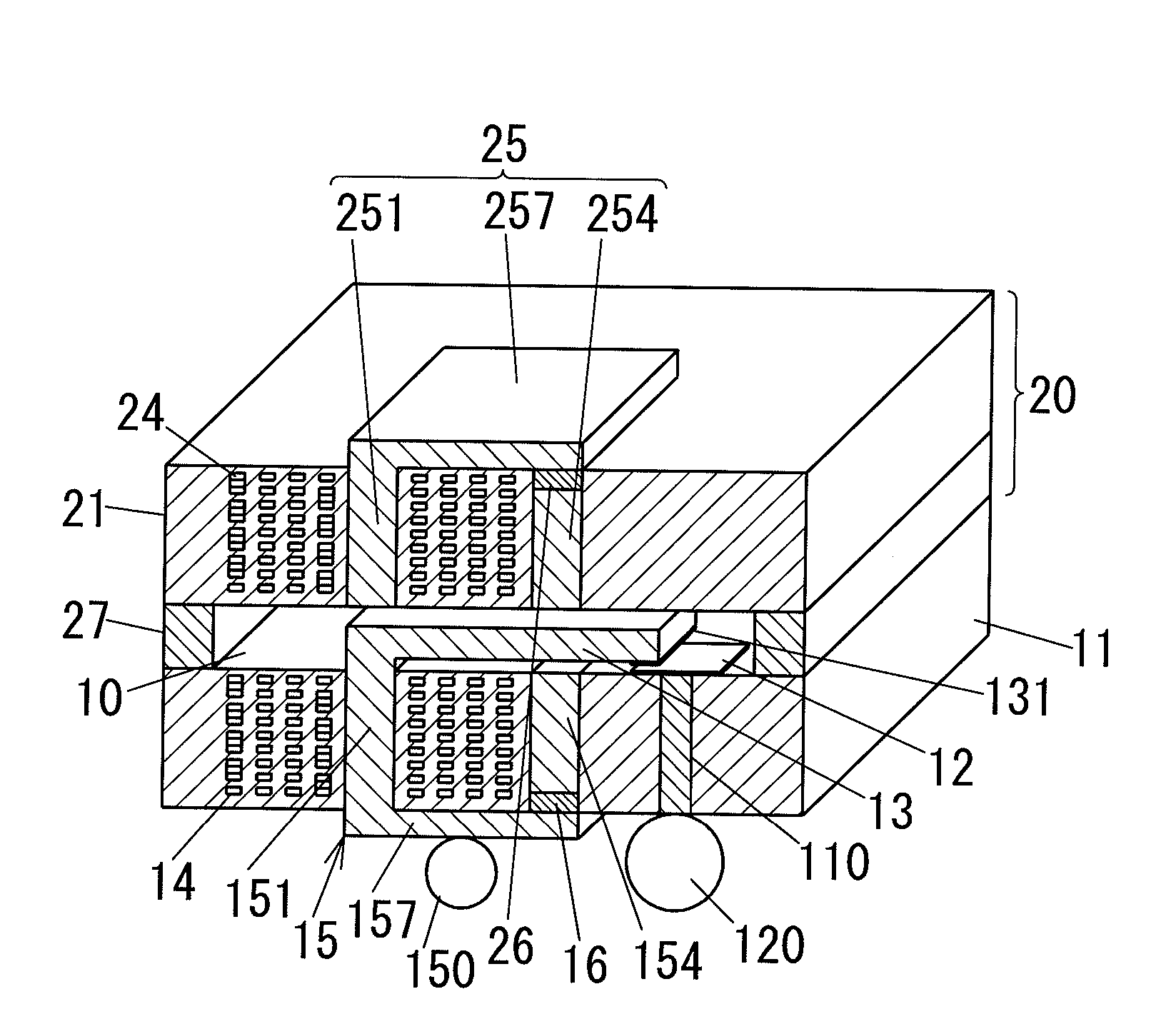
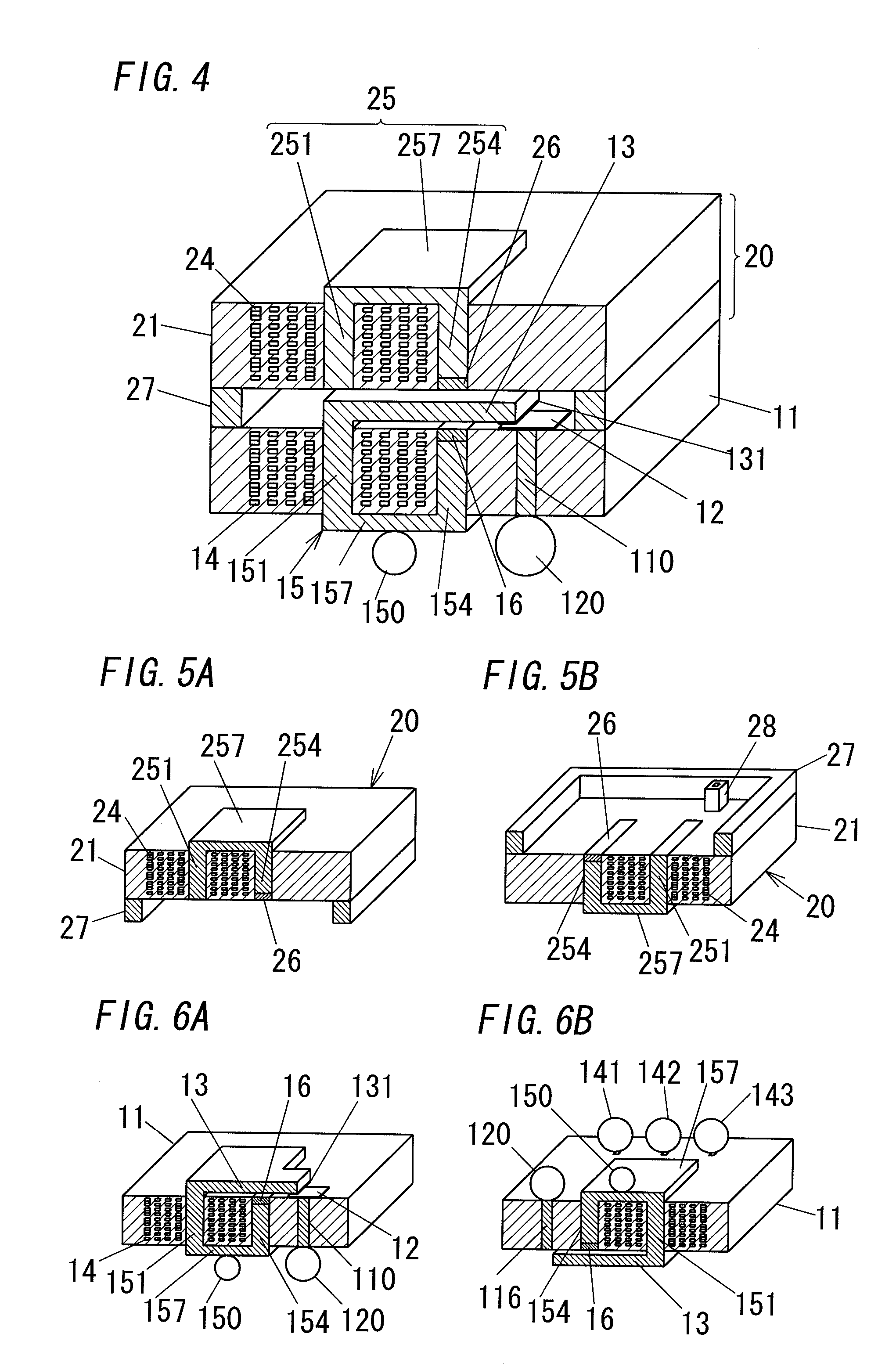
[0053]FIG. 4 shows a micro relay in accordance with a second embodiment of the present invention. For the purpose of clarity, like kind elements are assigned the same reference numerals as depicted in the first embodiment. In place of the cover 2 of the first embodiment, the micro relay in the second embodiment includes a cover 2 formed of a second substrate 21, a coil 24, a magnetic member 25, a permanent magnet 26 and a spacer 27.

[0054]In the second embodiment, the second substrate 21 is a laminated substrate (e.g., LTCC) like the main substrate 11 of the first embodiment. The coil 24 is formed of a plurality of (nine in FIG. 4) planer coils connected in series like the coil 14 of the first embodiment.

[0055]The magnetic member 25 has a core 251, a first yoke 254 and a second yoke 257. Each of the core 251, first yoke 254 and second yoke 257 is a flat piece of a magnetic substance. First and second ends of the core 251 are flush with one side (an upper surface) and the other (a low...

third embodiment

[0060]FIG. 7 shows a micro relay in accordance with a third embodiment of the present invention. For the purpose of clarity, like kind elements are assigned the same reference numerals as depicted in the first embodiment.

[0061]In the first embodiment, the permanent magnet 16 (magnetic substance) is formed of well known material having large coercive force in and above the cavity by a deposition method such as an aerosol deposition method, a pulsed laser deposition method, a plating method, a screen print method or the like. However, the magnet 16 comes to have a comparatively small magnetic force, and accordingly the magnet 16 needs to be made larger, so that the permanent magnet occupies larger part in the above-mentioned closed magnetic path. Because of this, the number of turns of the coil is increased and the size of the micro relay is increased.

[0062]If the permanent magnet 16 is a sintered magnet, the sintered magnet has a comparatively large magnetic force and therefore the m...


PUM


Abstract

A micro relay includes a magnetic member and a permanent magnet in addition to a main substrate, a stationary contact, an armature and a coil. The magnetic member includes a core located in a first though hole of the main substrate. The permanent magnet is located at an end of the magnetic member or at a place within the magnetic member. The main substrate has a plurality of laminated layers. The coil is formed of a plurality of planer coils connected in series. The plurality of planer coils are formed on the plurality of laminated layers, respectively and are located around the core.

Description

TECHNICAL FIELD[0001]The invention relates generally to micro relays and more particularly to a micro relay incorporated in a substrate.BACKGROUND ART[0002]In general, an electromagnetic relay has a coil, a yoke, a permanent magnet, an armature, a stationary contact and a movable contact, and is configured to make or break an electric contact between the contacts by energizing the coil to move the movable contact through the armature. Small-sized micro relays are manufactured by using semiconductor process technology.[0003]For example, a latching relay described in U.S. Pat. No. 6,894,592 issued on May 17, 2005 includes a substrate, an insulating layer, a contact (a stationary contact), a staging layer, a cantilever (an armature) and a magnet. The insulating layer is placed on one side (an upper surface) of the substrate and houses a conductor. The conductor is arranged in a coil pattern (hereinafter referred to as a “coil”). The stationary contact is placed on one side (an upper su...

Claims


Application Information

Patent Timeline
Patent Type & Authority Applications(United States)
IPC IPC(8): H01H45/00
CPCH01H50/005H01H2001/0042H01H2050/007B81B3/00H01H51/22
Inventor HAGIHARA, YOSUKEHASHIMOTO, TAKESHIUOTOME, RIICHIENOMOTO, HIDEKIKAKIMOTO, KATSUMIYOKOYAMA, KOJIKISHIMOTO, SHINICHI
Owner MATSUSHITA ELECTRIC WORKS LTD
Why Eureka
Try Eureka