Solid State Components Having an Air Core

US20100182118A1Active Publication Date: 2010-07-22ROSKOS HENRY

Image

  • Solid State Components Having an Air Core
  • Solid State Components Having an Air Core
  • Solid State Components Having an Air Core

Examples


Embodiment Construction

[0022]Suitable techniques for manufacturing inductive components are described in co-owned U.S. patent application having Ser. No. 09 / 965297, also incorporated by reference in its entirety.

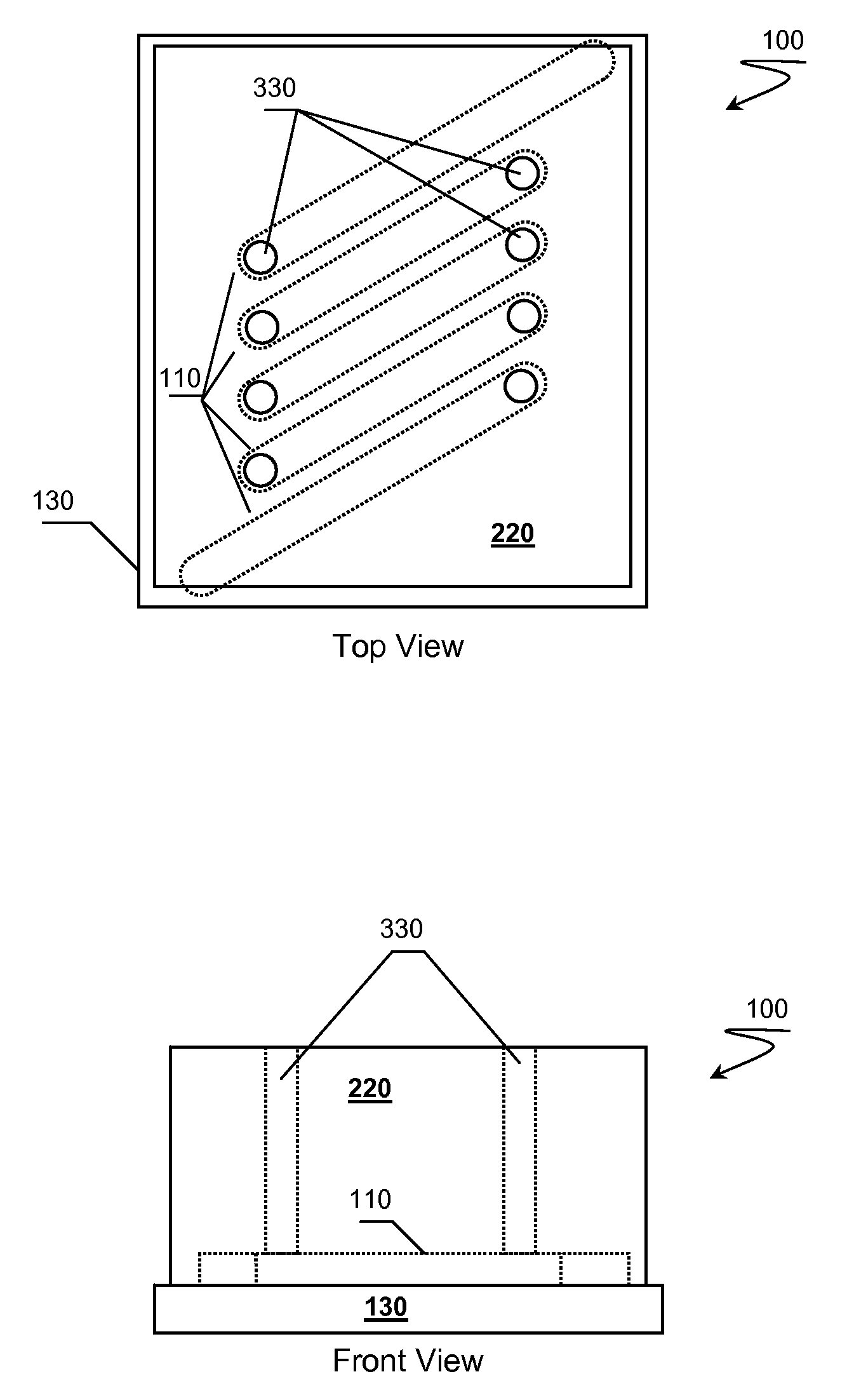
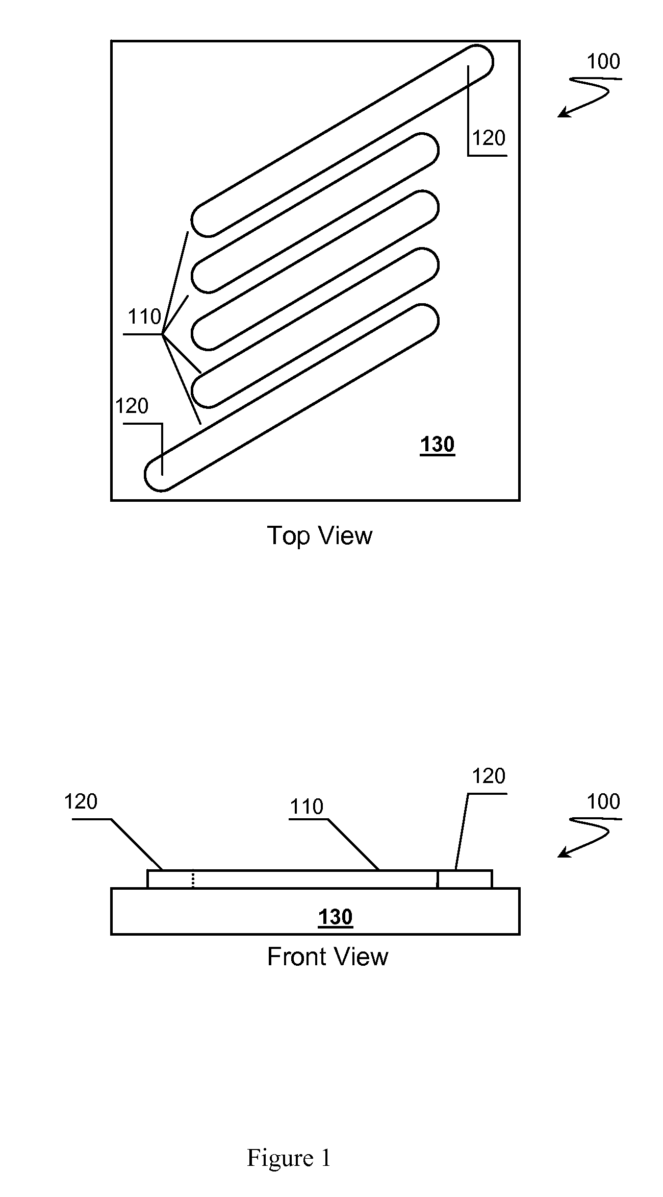
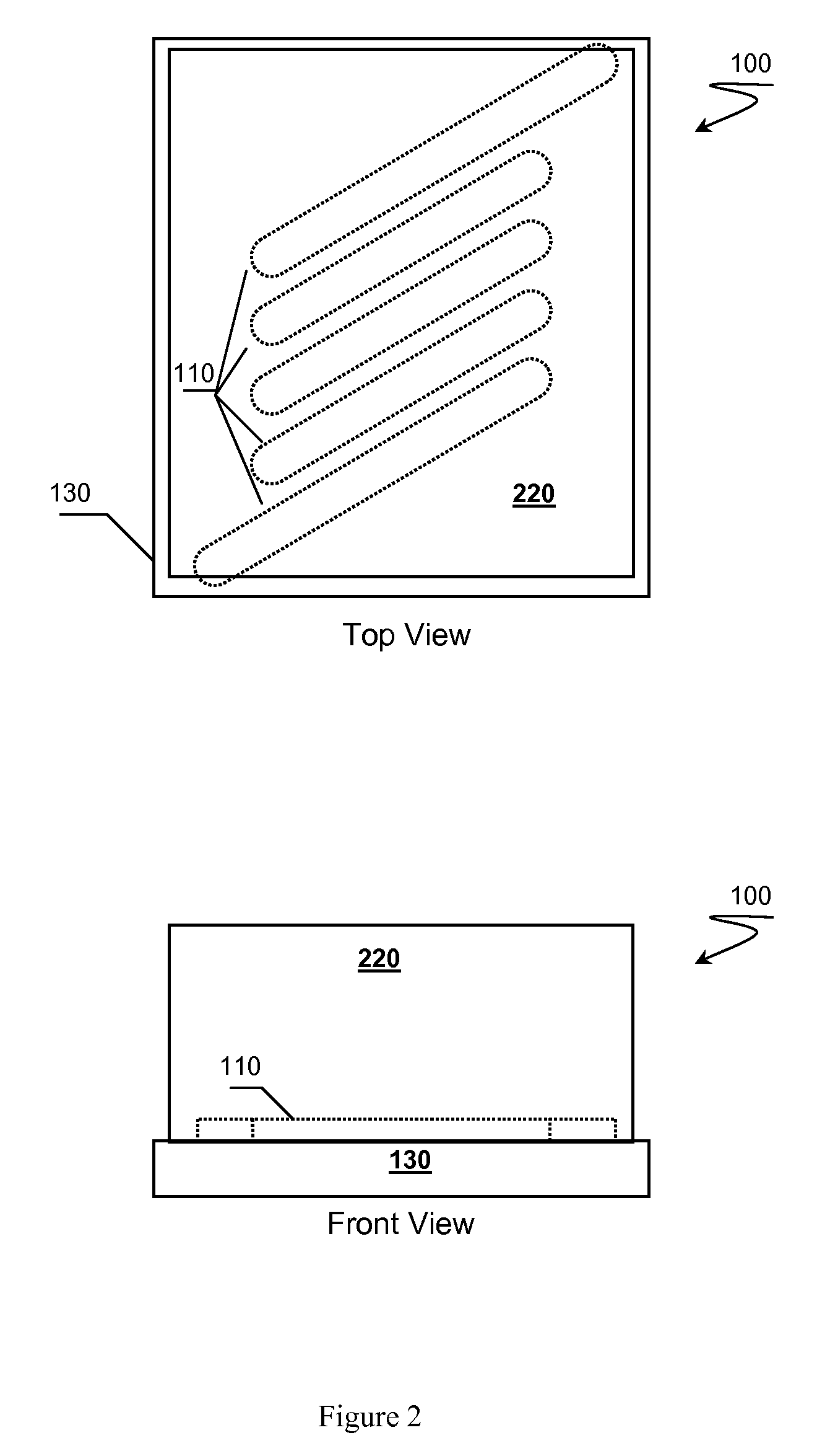
[0023]In FIG. 1, a top view and front view of inductor 100 is presented showing an initial stage of manufacturing. A plurality of lower conducting bands 110 are placed on substrate 130. Preferably, at least two of the lower bands providing inductor contacts 120.

[0024]Substrate 130 preferably comprises a semiconductor. Acceptable semiconductors include silicon (Si), doped silicon, gallium arsenide (GaAs), or other semiconductors commonly used in manufacture of ICs.

[0025]It is contemplated that an insulator layer (not show) can also be present between the lower conducting bands and substrate as is commonly used in micro component manufacturing processes. Typically, insulators include oxides, nitrides, spin on glass (SOG), or other insulators. An insulating layer can be grown or deposited using known...


PUM


Abstract

Solid state components having an air core and methods of producing such components are presented. An air core component preferably has lower conducting bands, upper conducting, and conducting posts that collectively form a conducting coil. A coating material placed at least over the upper bands of the coil provides structural support for the coil. The coil can be built around or in a sacrificial core material that can be removed leaving an air core behind.

Description

RELATED APPLICATIONS[0001]This application relates to U.S. patent application having Ser. No. 09 / 965,297 filed on Sep. 28, 2001, now abandoned. This and all other extrinsic materials discussed herein are incorporated by reference in their entirety. Where a definition or use of a term in an incorporated reference is inconsistent or contrary to the definition of that term provided herein, the definition of that term provided herein applies and the definition of that term in the reference does not apply.FIELD OF THE INVENTION[0002]The field of the invention is solid state component technologies.BACKGROUND [0003]There is a strong desire for developing high-Q inductors at ever smaller sizes using existing integrated circuit (IC) manufacturing techniques. However, current state of the art techniques require modification to IC processing technologies that are impractical for one reason or another. For example, the industry has a long felt need for creating air core inductors or transformer...

Claims


Application Information

Patent Timeline
22 Jul 2010
Publication
US20100182118A1
IPC
H01F5/00
CPC
H01F27/323; H01F17/02
Inventors
ROSKOS, HENRY; JOHNSON, FREDRICK QUINCY