Method of surface seismic imaging using both reflected and transmitted waves

a technology of transmitted waves and reflected waves, applied in the field of surface seismic data processing, can solve the problems of limited practical efficiency of such an approach, inability to realistically process actual seismic data, and insufficient primary reflections to generate unambiguous images, so as to improve the reliability and stability of imaging boundaries, improve forecasting efficiency, and expand the information base available

Active Publication Date: 2010-07-22
TETRASEIS INC
View PDF1 Cites 19 Cited by
  • Summary
  • Abstract
  • Description
  • Claims
  • Application Information

AI Technical Summary

Benefits of technology

[0025]In accordance with the method of the invention, in transmitted-reflected wave migration (“TWM”), transmitted waves are used in surface seismic for the first time and in a manner that expands the information base available to those engaged in seismic prospecting so as to result in the following advantages: it is now possible to produce images of boundaries at almost any angle of inclination using information about reflected reflected-transmitted waves (combined with velocity and other standard geologic information) processed using continuation and correlational procedures; when forming images of elongate small-amplitude geologic discontinuities (such as faults, zones of fracturing, dykes, etc) transmitted-reflected wave migration procedures extract information from the fact that conversion can occur as transmitted waves pass through such discontinuities; and the new migration procedure based on transmitted-reflected waves is also more efficient than conventional methods because it takes into account more of the parameters that define the physical properties of geologic formations.
[0026]Further, example applications for and advantages of the method of the invention include: forecast the presence of gas deposits in vertical contacts, in particular, salt domes and clastic deposits, improve the reliability and stability of imaging boundaries near a salt dome, expand the dip-angle imaging range from horizontal to vertical boundaries, improve efficiency in forecasting gas saturation in isotropic formations, improve efficiency in forecasting fractured reservoirs by using reflected-transmitted converted waves in azimuthal seismic observations.

Problems solved by technology

However, for steeply sloping reflectors, outside such limited range, primary reflections are insufficient to generate unambiguous images revealing their existence, position, and orientation with an acceptable level of certainty.
However, precise delineation of salt stocks, tracing of faults, and other problems connected with near-salt sediments, often still result in ambiguous solutions likely because the sub-vertical reflecting boundaries have rugose surfaces.
However, the practical efficiency of such an approach is limited, because in the boreholes, such reflections can only be recorded within depth intervals deeper than the target boundary.
Consequently, while it is difficult to use phase-shift analysis (because of the low resolving power of known conventional seismic processing methods) duplex waves can in theory also be used to identify and trace faults with small displacements.
McMchan, G. A. (in his 1983 Article, Migration by extrapolation of time-depended boundary values: Geophys. Prosp., 31, 412-420) describes imaging vertical boundaries based on reverse time migration, however according to that method all the primary reflections were removed from the gathers, which is not realistic in processing actual seismic data.
However, transmitted waves within framework of the interferometric approach are not used in any known method of the surface seismic surveys.
However, in complex geological conditions, the obtained information from reflected waves is not enough for a confident interpretation of gas saturation.
Disadvantageously, duplex wave migration procedures that are based only on reflected waves are somewhat restricted to imaging sub-vertical boundaries with dip-angles ranging from 60-90 degrees from the horizontal axis.

Method used


Image

  • Method of surface seismic imaging using both reflected and transmitted waves
  • Method of surface seismic imaging using both reflected and transmitted waves
  • Method of surface seismic imaging using both reflected and transmitted waves

Examples


example 1

Forecast the Presence of Gas Deposits in Vertical Contacts, in Particular, Salt Domes and Clastic Deposits

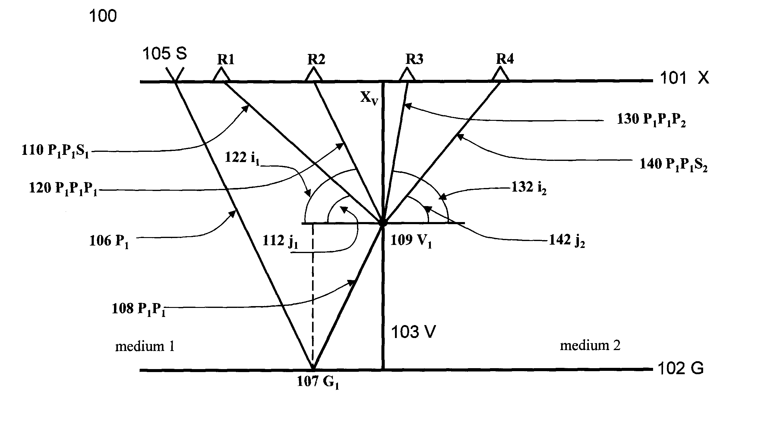
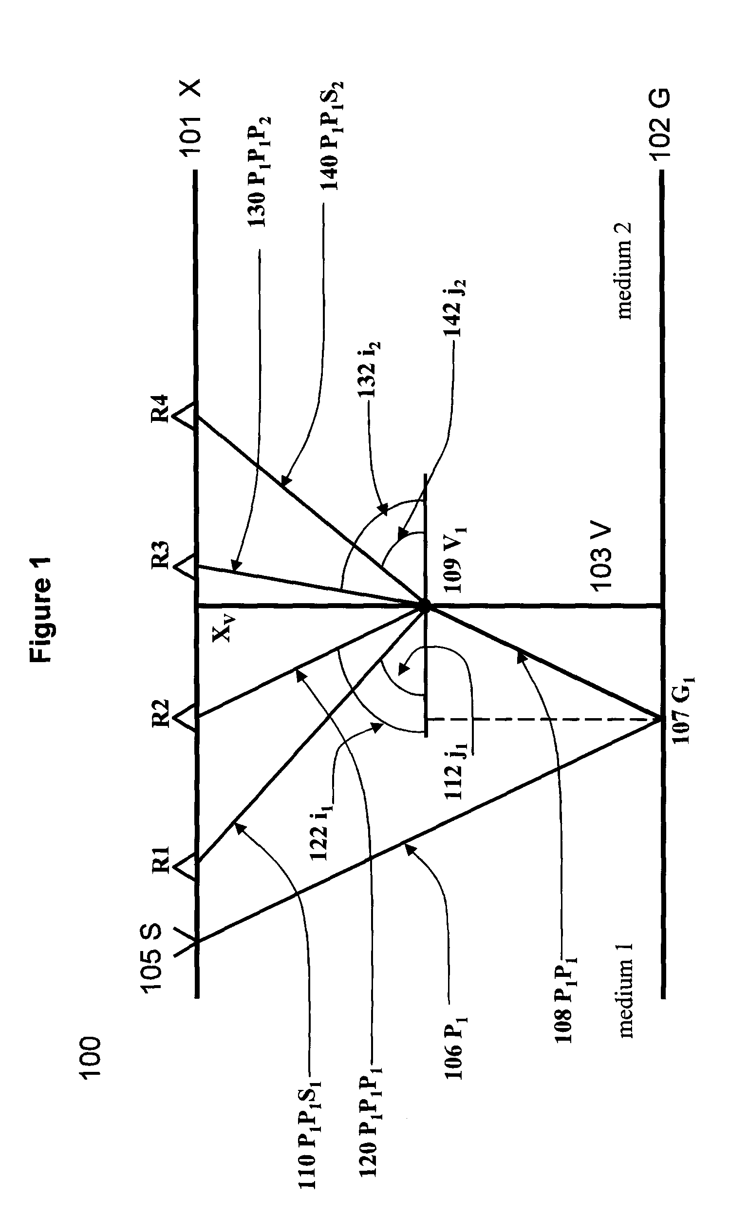
[0046]The amplitudes of the reflected and transmitted waves on the vertical contact of two media are at a fixed incident angle i, however, using common shot gathers, one cannot provide separate images characterized by a constant incident angle at the vertical boundary. Thus the image is formed using the four types of waves and it is useful to keep the incident angle at the sub-vertical boundary constant. Thus, imaging the vertical boundary can be considered the first step in determining medium parameters, so the location and inclination of the sub-vertical boundary, typically unknown, are determined. Once the geometry of the boundary is determined, we proceed to the second stage—determination of Poisson's ratio across the contacting media.

[0047]Referring now to FIG. 1, as seen in the ray drawing generally denoted as 100, a surface 101 (also denoted as “X”) and a horizontal base ...

example 2

Imaging a Thin Vertical Layer Interrupting a Given Media

[0096]Referring now to FIG. 4 we consider the case of thin vertical layer 410 (e.g. a fractured zone or an intrusion of either salt or igneous rocks, etc.) interrupting a given media. Similar to the manner explained and shown in FIG. 1, a downward traveling wave 106 incident on layer 410 will create four types of waves. Migration of compressional transmitted waves does not assist with this case, since the velocity before and after the sub vertical layer is the same. However, converted transmitted waves do assist us because their velocity differs. Select the seismogram for source 105 S and downward continue it to level Zi with the shear wave velocity of the medium, ignoring thin vertical layer 410 for the moment due to its small contribution to the velocity model. By applying DWM and selecting the seismic image I with compressional wave velocities we obtain an image of thin vertical layer 410 formed using reflected and transmitt...

example 3

Imaging Layers Having Arbitrary Dip-Angles

[0107]Advantageously, migration of transmitted converted duplex waves can be used to form images of both sub vertical and horizontal layers (i.e. layers of arbitrary dip-angle) having practically an unlimited range of dip angles. As explained above, we select the zone between the shot-receiver locations when using converted transmitted duplex waves for imaging. Images of both sub vertical and horizontal boundaries may be formed simultaneously.

[0108]Referring now to FIG. 7 we see an example of seismic imaging based on converted transmitted duplex waves, where image 701 is the model of upward-thinning layer and a number of horizontal discontinuities, and image 702 shows a vertical layer constructed using transmitted converted duplex waves and formed at X=4000M, such that both vertical and horizontal layers correspond to the model. It may be observed in FIG. 7 that artifacts appear close to the vertical layer, thereby complicating the image of ...


PUM


Abstract

Reflected-transmitted non-converted and converted seismic waves as used for seismic imaging which is not limited by the angle of inclination of the seismic interfaces. These wave signals are recorded at the surface and are later used to obtain seismic imaging of geological discontinuities and the physical properties of the medium. Known duplex waves are used with transmitted waves for obtaining seismic images from much wider angles, ranging from horizontal to vertical. Two types of migration procedures are used: the first one being based on migration of transmitted compressional and converted duplex waves, and the second one being based on the joint migration of two interrelated fields, such as interferometric principles; for example, the first field of primary waves corresponding to the one time reflected monotypic compressional (non-converted) type of waves and a second wavefield corresponding to secondary waves of more complex origin, such as reflected waves and converted waves.

Description

FIELD OF THE INVENTION[0001]The invention relates generally to surface seismic data processing and more particularly, to seismic imaging that does not limit the angle of inclination of the seismic interfaces, and estimation of Poisson's ratio and fracture parameters in geological interface contacts without limiting the angle of inclination of these contacts. Two types of migration procedures are implemented: based on migration of transmitted and converted duplex waves, and based on the joint migration of compressional and converted duplex waves.BACKGROUND OF THE INVENTION[0002]Conventional seismic data processing methods are based on detecting primary reflections using a line (2D) or a grid (3D) of receivers placed on or near the surface of a zone of interest. The position of each receiver in the group is known relative to a source of seismic energy, which when triggered creates mechanical waves, which in turn activate electro-mechanical transducers that are an element of each recei...

Claims


Application Information

Patent Timeline
Patent Type & Authority Applications(United States)
IPC IPC(8): G06K9/00G06T11/20
CPCG01V1/28G01V2210/679G01V2210/51G01V2210/67
Inventor MARMAL YEVSKYY, NAUMGORNYAK, ZYNOVIYKOSTYUKEVCH, ALEXANDERROGANOV, YURIMERSHCHIY, VICTOR
Owner TETRASEIS INC
Why Eureka
Try Eureka