Rogue onu detection via photonic mixing

a technology of photonic mixing and rogue onus, applied in the field of optical network units, can solve the problems of unsuitable rogue onus, difficult detection and troubleshooting, and possible interference between upstream light sources

Inactive Publication Date: 2010-07-22
WSOU INVESTMENTS LLC
View PDF2 Cites 8 Cited by
  • Summary
  • Abstract
  • Description
  • Claims
  • Application Information

AI Technical Summary

Problems solved by technology

These rogue ONUs are undesirable and very difficult to detect and troub

Method used


Image

  • Rogue onu detection via photonic mixing
  • Rogue onu detection via photonic mixing
  • Rogue onu detection via photonic mixing

Examples


Embodiment Construction

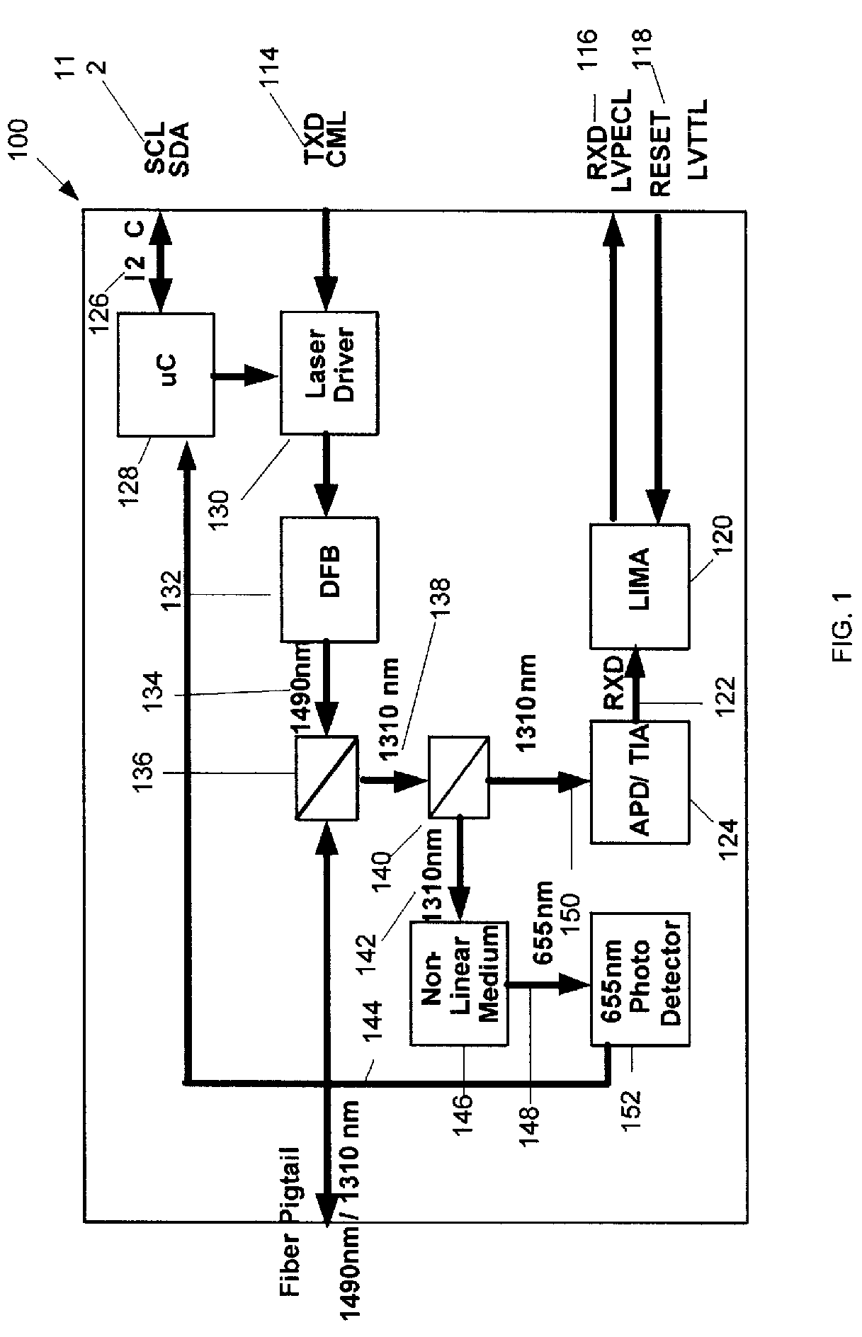
[0016]Referring now to FIG. 1, a system 100 for rogue ONU detection via photonic mixing is depicted. The system 100 is an LT Optical Module comprising a number of components utilized for rogue ONU detection. Serial Clock (SCL) and Serial Data (SDA) 112 signals are transmitted via Inter-Integrated Circuit (I2C) communication 126 with a microcontroller (uC) 128. The microcontroller controls a Laser Driver 130, which itself also receives Transmitted Data (TXD) and Current Mode Logic (CML) signals 114. The laser driver drives a Distributed Feedback Laser (DFB) 132 which creates a 1490 nanometer (nm) downstream beam 134. This beam reaches the Wavelength Division Multiplexer (WDM) 136 which allows for two-way traffic on a single optical fiber, with downstream traffic at 1490 nm and upstream at 1310 nm. The WDM 136 transmits the downstream beam and receives the upstream beam from a PON (not shown) via a fiber pigtail 144. The 1310 nm upstream beam 138 continues from the WDM 136 into a seco...


PUM


Abstract

A system, method, and computer readable medium for rogue Optical Network Unit (ONU) detection via photonic mixing, comprises a first Wavelength Division Multiplexer (WDM), a second WDM communicably coupled to the first WDM, a non-linear medium communicably coupled to the second WDM, and a photodetector communicably coupled to the non-linear medium, wherein the first WDM transmits a first upstream beam and a second upstream beam to the second WDM, wherein the first upstream beam is a normal upstream beam and wherein the second upstream beam is a rogue upstream beam, wherein the second WDM transmits the normal upstream beam and the rogue upstream beam to the non-linear medium, wherein the non-linear medium mixes the normal upstream beam and the rogue upstream beam resulting in a mixed beam, wherein the non-linear medium transmits the mixed beam to the photodetector, and wherein the photodetector analyzes the mixed beam to indicate the presence of a rogue ONU.

Description

BACKGROUND OF THE INVENTION[0001]The present disclosure is generally related to Optical Network Units (ONUS), and more particularly to the detection of rogue ONUs using photonic mixing.[0002]The present disclosure is related to rogue ONUs on a Passive Optical Network (PON). Rogue ONUs are devices on the PON that transmit upstream when they are not supposed to. These rogue ONUs are undesirable and very difficult to detect and troubleshoot.[0003]A PON is a point-to-multipoint, fiber to the premises network architecture in which unpowered optical splitters are used to enable a single optical fiber to serve multiple premises. At the source of a PON is an Optical Line Terminal (OLT), typically residing at a service provider's central office (CO). Downstream from the OLT are a number of ONUs, typically near end users. The OLT can be viewed as the source and the ONUs as the multiple destinations. These ONUs can be connected in a star arrangement using optical splitters, which reside at a p...

Claims


Application Information

Patent Timeline
IPC IPC(8): H04B10/08
CPCH04B10/0773H04J14/0282H04J14/0247H04J14/0252
Inventor DALTON, RODGERTEETER, JASONBAGHDADI, JIHAD
Owner WSOU INVESTMENTS LLC
Why Eureka
Try Eureka