Methods and systems for monitoring the operation of a robotic actuator

a robotic actuator and monitoring system technology, applied in the field of robotic arm end actuators, can solve the problems of hammering the operation and efficiency of tool changers and tools so controlled, communication protocols that are unacceptable for high-speed connections and disconnections, and protocols limited in their monitoring ability, so as to reduce the connection time

Inactive Publication Date: 2010-07-22
APPLIED ROBOTICS
View PDF19 Cites 20 Cited by
  • Summary
  • Abstract
  • Description
  • Claims
  • Application Information

AI Technical Summary

Benefits of technology

[0014]A further aspect of the invention is a method for reducing the connection time between a robot-side component and the tool-side component of a robot tool changer, the method including or comprising: energizing at least one device adapted to store at least some information about the tool-side component; coupling the robot-side component with the tool-side component; and communicating at least some date from the energized device to the robot side component. In one aspect, energizing may comprise providing a power supply, for example, a rechargeable power supply, such as, a capacitor, coupled to the at least one device to the tool-side component.

Problems solved by technology

However, though the DeviceNet protocol is a generally accepted communications protocol in the automation industry, DeviceNet and related protocols are characterized by disadvantages that may hamper the operation and efficiency of tool changers and tools so controlled.
For example, the present applicants found such communications protocols unacceptable for the high-speed connections and disconnections and performance information gathering requirements typically encountered in this competitive industry.
Moreover, the applicants also found such protocols limited in their ability to monitor, collect, and report certain operating parameters of tool changers and tools.

Method used


Image

  • Methods and systems for monitoring the operation of a robotic actuator
  • Methods and systems for monitoring the operation of a robotic actuator
  • Methods and systems for monitoring the operation of a robotic actuator

Examples


Embodiment Construction

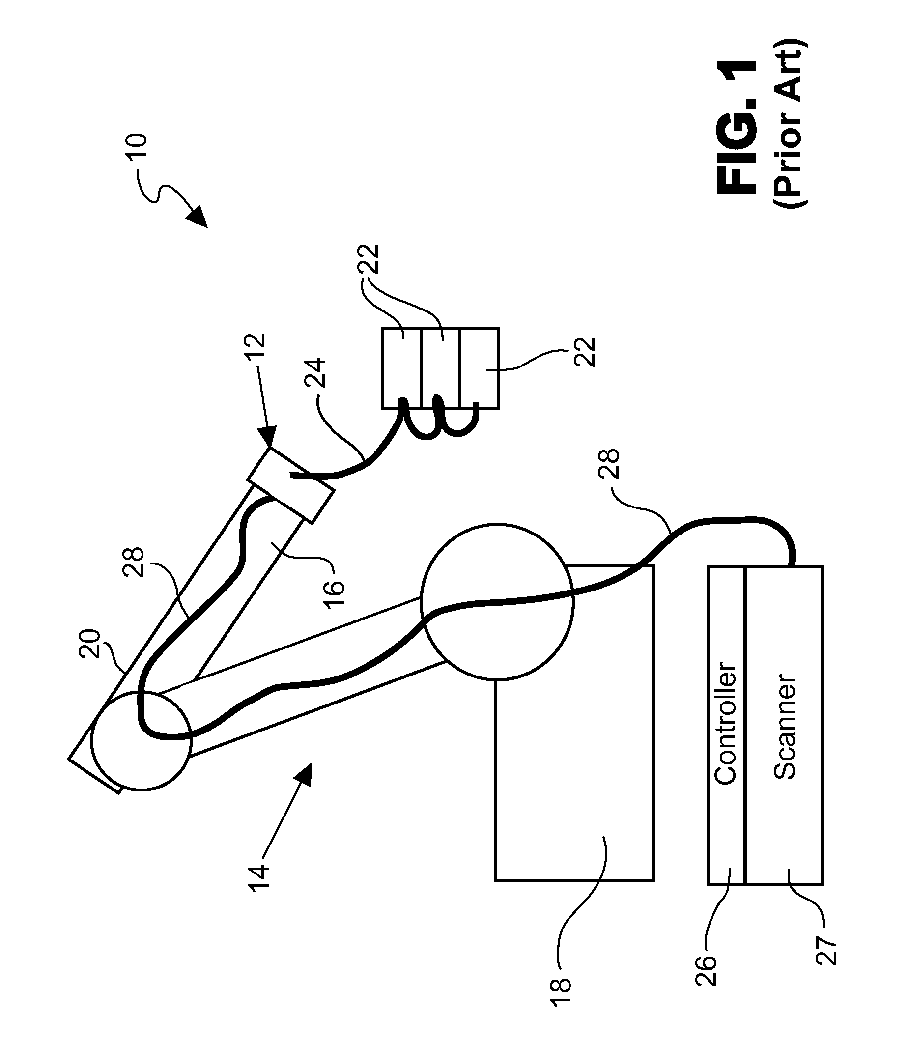
[0025]FIG. 1 is a schematic diagram of a system 10 for controlling the operation of a robotic actuator 12, for example, a tool changer, according to the prior art. As shown in FIG. 1, system 10 includes a robot 14 having an arm end 16 to which actuator 12 is typically mounted. As is typical, robot 14 includes a base 18 and an articulating arm 20 having arm end 16. As is typical of the prior art, actuator 12 is designed to engage and communicate with a plurality of tools 22, for example, manipulators, welders, and the like, which can be positioned by robot 14. Though the mechanical engagement of actuator 12 with tools 22 may be effected by a broad array of mechanical couplings, the electrical communication, for example, data and / or control signals, between actuator 12 and each of tools 22 is represented by bus 24.

[0026]According to the prior art, the operation of the robot 14, of the actuator 12, and of the tools 22 is typically controlled by a controller 26. Controller 26, for examp...


PUM


Abstract

A robotic tool changer and systems and methods for controlling the operation of a robotic tool changer are provided. The tool changer, methods, and systems include a robot-side component mountable to a robot arm end interface; a tool-side component adapted to engage a tool; a first slave module associated with the robot-side component and adapted to communicate with a first master module; and a second master module associated with the robot-side component and adapted to communicate with a second slave module associated with the tool. The second slave module may include a temporary power supply, for example, a battery or a capacitor, for instance, a super capacitor. Aspects of the invention are advantageous for performing high-speed robotic connections and disconnections, and for providing tool and tool changer performance information gathering.

Description

CROSS-REFERENCE TO RELATED APPLICATION[0001]This application claims priority from pending U.S. Provisional Patent Application 61 / 146,214, filed on Jan. 21, 2009, the disclosure of which is included by reference herein in its entirety.BACKGROUND OF THE INVENTION[0002]1. Field of the Invention[0003]The present invention generally relates to robotic arm end actuators and their control. More particularly, the present invention relates to methods and systems for operating and communicating to and from tools to optimize tool performance.[0004]2. Description of Related Art[0005]In the art of automation control, for example, the control of robots and robot-like manipulators, the robot, the robotic tool changer, and the tools handled by the robot are typically controlled by a controller, for example, a programmable logic controller (PLC) or computer. The communication between the controller and these components is typically made via a cable or bus, for example, a controller-area network (CAN...

Claims


Application Information

Patent Timeline
Patent Type & Authority Applications(United States)
IPC IPC(8): B23Q3/155
CPCB25J15/04B25J19/005Y10T483/15
Inventor WILLIAMS, JENNIFERCOOPER, CLAY C.BOWMAN, MICHAEL F.RINALDI, JOHN
Owner APPLIED ROBOTICS
Why Eureka
Try Eureka