Check patentability & draft patents in minutes with Patsnap Eureka AI!

Movement detection during radiation treatment using a radar system

Inactive Publication Date: 2010-07-22
SIEMENS AG
View PDF9 Cites 9 Cited by
  • Summary
  • Abstract
  • Description
  • Claims
  • Application Information

AI Technical Summary

Benefits of technology

[0009]The position is detected during irradiation of the patient. The radar system or radar systems are designed and / or oriented such that the radar system or radar systems do not suffer any damage from the radiation. Accordingly, the irradiation does not have to be interrupted in order to undertake the position detection using the radar system or the radar systems. The irradiation can be adapted in an uninterrupted manner to a change in the position of the patient in the irradiated body region of the patient.
[0014]One, two, or more radar systems can be used. The radar systems can emit their primary radiation onto the patient at different angles, for example, not in parallel to each other. This increases the local resolution.
[0015]In one embodiment, a control device is present for adjusting and / or interrupting the beam emitted by the radiation source as a result of the detected position of the patient or the part of the patient. The control device may be connected to the evaluation unit and controls the beam as a function of results of the evaluation unit. The adjustment of the beam corresponds to a change in its direction, whereas its interruption represents an at least temporary switching off of the beam. Such measures are especially advantageous if it is established that the position of the patient or of organs of the patient have changed. This enables the irradiation of a patient in undesired regions to be avoided. By suitably adjusting the beam, despite changes in a position of the patient or the part of the patient, the same section of the body can be irradiated.
[0018]In addition or as an alternative to two evaluation units, an evaluation unit can be present for determining breathing and / or heart activity of the patient from data detected by the at least one radar system. This makes it possible to dispense with all or some of the devices for observing breathing and pulse of the patient during irradiation.

Problems solved by technology

A change in the position of the patient leads to this condition no longer being fulfilled.
This leads to an undesired irradiation of healthy tissue.

Method used


Image

  • Movement detection during radiation treatment using a radar system
  • Movement detection during radiation treatment using a radar system

Examples


Embodiment Construction

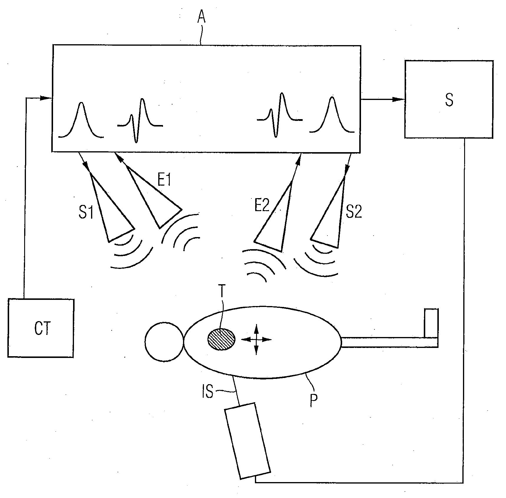
[0027]FIG. 1 shows a patient P who is being irradiated by an ion beam IS during particle therapy. The ion beam IS can be a beam of carbon ions, for example. A proton beam can also be employed. The objective of the irradiation is that the ion beam IS reaches the patient's tumor T and destroys the tumor T. The control device S serves to control the deflection of the ion beam IS in different directions. Using magnets, the direction of the ion beam IS can be changed by the control device S so that the ion beam IS can be directed precisely onto the tumor. Deflection of the ion beam IS is illustrated by the two double-ended arrows next to the tumor T.

[0028]During irradiation, the ion beam IS is aligned exactly on the tumor T and hits the target volume corresponding to the tumor T. A displacement of the ion beam IS by just a few millimeters would destroy parts of the healthy tissue and allows parts of the tumor T to survive, which would promote the continuance of the tumor T. Accordingly, ...


PUM


Abstract

The present embodiments relate to irradiating a patient with an irradiation source directed onto the patient, as well as with a radar system for detecting the position of the patient or a part of the patient during the irradiation.

Description

[0001]The present patent document claims the benefit of the filing date of DE 10 2009 005 110.4 filed on Jan. 19, 2009, which is hereby incorporated by reference.BACKGROUND[0002]The present embodiments relate to irradiating a patient with a radiation source directed onto the patient.[0003]In particle therapy, which can be used for therapy of cancers, a tumor is irradiated precisely with a proton or an ion beam. In contrast to irradiation with electromagnetic beams, with ion irradiation the majority of the beam energy is discharged directly in the tumor. The tissue lying above the tumor incurs less damage. The chances of healing are no worse than with a therapy with other beams but far fewer side effects arise. Frequently carbon and neon ions are used.[0004]In order to damage as little healthy tissue as possible, the patient is supported so that the particles interact with the desired region of the body, for example, with the tumor tissue, and as little as possible with the healthy t...

Claims


Application Information

Patent Timeline
IPC IPC(8): A61B5/0205A61N5/10G01S13/00
CPCA61N5/1049A61N5/1064A61N5/1067A61N2005/1061A61N2005/1087
Inventor SAAR, MATTHIAS
Owner SIEMENS AG
Features
  • R&D
  • Intellectual Property
  • Life Sciences
  • Materials
  • Tech Scout
  • Unparalleled Data Quality
  • Higher Quality Content
  • 60% Fewer Hallucinations
Learn More