Method for estimating the wear of a tire

a tire wear and tire technology, applied in vehicle tyre testing, roads, instruments, etc., can solve the problems of lowering the draining performance and longer braking distance on wet road surfaces, excessive wear, and marked drop in grip performance on icy or snow-covered roads, etc., to achieve high-precision estimation of tire wear and deformation, and accurate detection of the amount of tread deformation

Active Publication Date: 2010-07-29
BRIDGESTONE CORP
View PDF18 Cites 52 Cited by
  • Summary
  • Abstract
  • Description
  • Claims
  • Application Information

AI Technical Summary

Benefits of technology

[0036]According to a twenty-third aspect of the present invention, there is provided a method for estimating the wear of a tire, wherein the sensor is an acceleration sensor and the index of the amount of deformation is calculated using a time-series waveform of the radial acceleration of the tire tread detected by the acceleration sensor. The acceleration sensor is a highly responsive sensor as described earlier. Therefore, placing the sensor in position to detect the radial acceleration of the tire tread will allow an accurate detection of the amount of deformation of the tread and in consequence a highly accurate estimation of the degree of tire wear.
[0037]According to a twenty-fourth aspect of the present invention, there is provided a method for estimating the wear of a tire, wherein the peak level of the time-series waveform of radial acceleration is calculated and the calculated peak level is used as the index of the amount of deformation. When the acceleration waveform represents the radial acceleration of the tire, the time-series waveform of the acceleration itself corresponds to the amount of deformation, so that the index of the amount of deformation can be calculated with excellent accuracy.
[0038]According to a twenty-fifth aspect of the present invention, there is provided a method for estimating the wear of a tire, wherein the relationship between the index of the amount of deformation and the degree of tire wear is determined beforehand and the degree of tire wear is estimated by comparing this predetermined relationship between the index of the amount of deformation and the degree of tire wear with the calculated index of the amount of deformation. As a result, the degree of tire wear can be estimated with even better accuracy. Note here that the index of the amount of deformation used in the relationship between the index of deformation amount and the degree of tire wear may be either the magnitude of the index or the amount of change in the magnitude from the start of use of the index. The magnitude of the index can change from that of a new tire, depending on factors in the fabrication of the tire and those in the installation of the sensor. In such a case, the constancy of estimation can be improved by measuring the value of the index at the start of use, calculating the amount of change from the initial value, and comparing them with the predetermined relationship.
[0039]According to a twenty-sixth aspect of the present invention, there is provided a method for estimating the wear of a tire, wherein the upper limit of tire speed in estimating the degree of tire wear is 100 km / h. This allows the tire wear to be estimated with excellent constancy. That is, in the present method, tire wear is estimated by obtaining information on the deformation of the tread, but above the tire speed of 100 km / h, the method will need a significant correction because at those speeds it is subject to an extremely large influence of centrifugal force. However, since tire wear is a very slow change over time, there is no problem with interruptions of estimation during high-speed running of the vehicle. Therefore, as described above, setting an upper limit of tire speed in estimating the degree of tire wear will enhance the constancy of estimation.

Problems solved by technology

Generally tire wear leads to lowered draining performance and longer braking distance on wet road surfaces.
Also, in the case of winter tires, wear can bring about a marked drop in grip performance on an icy or snow-covered road.
Furthermore, excessive wear can be very dangerous by allowing water to seep into the tread belts, which can eventually cause a rupture of the tire.
It has therefore been difficult to realize a constantly accurate estimation of tire wear from the difference in tire radius because of the necessity not only to measure with great accuracy but also to take into consideration various error factors in vehicular running such as the inner-outer wheel errors in cornering, errors due to acceleration slips at braking or drive, and errors due to inclinations of the road surface.

Method used


Image

  • Method for estimating the wear of a tire
  • Method for estimating the wear of a tire
  • Method for estimating the wear of a tire

Examples


embodiment 1

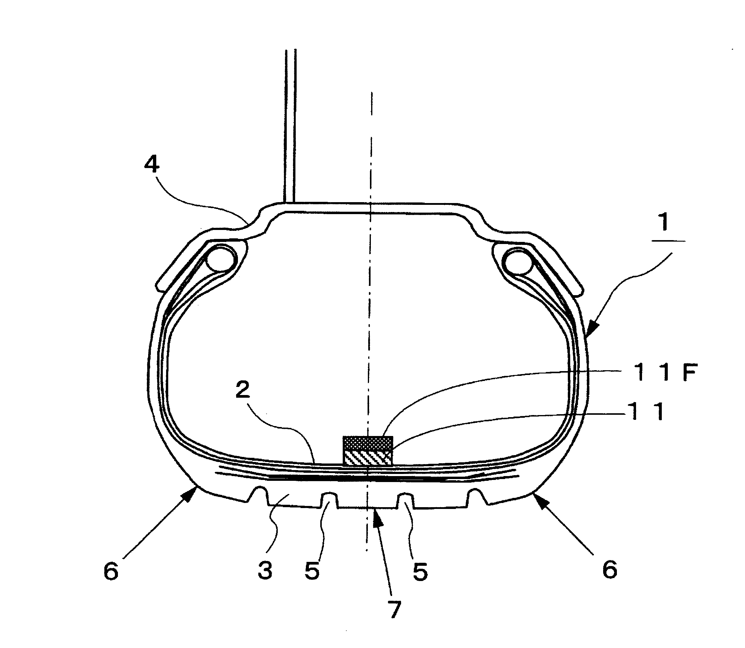
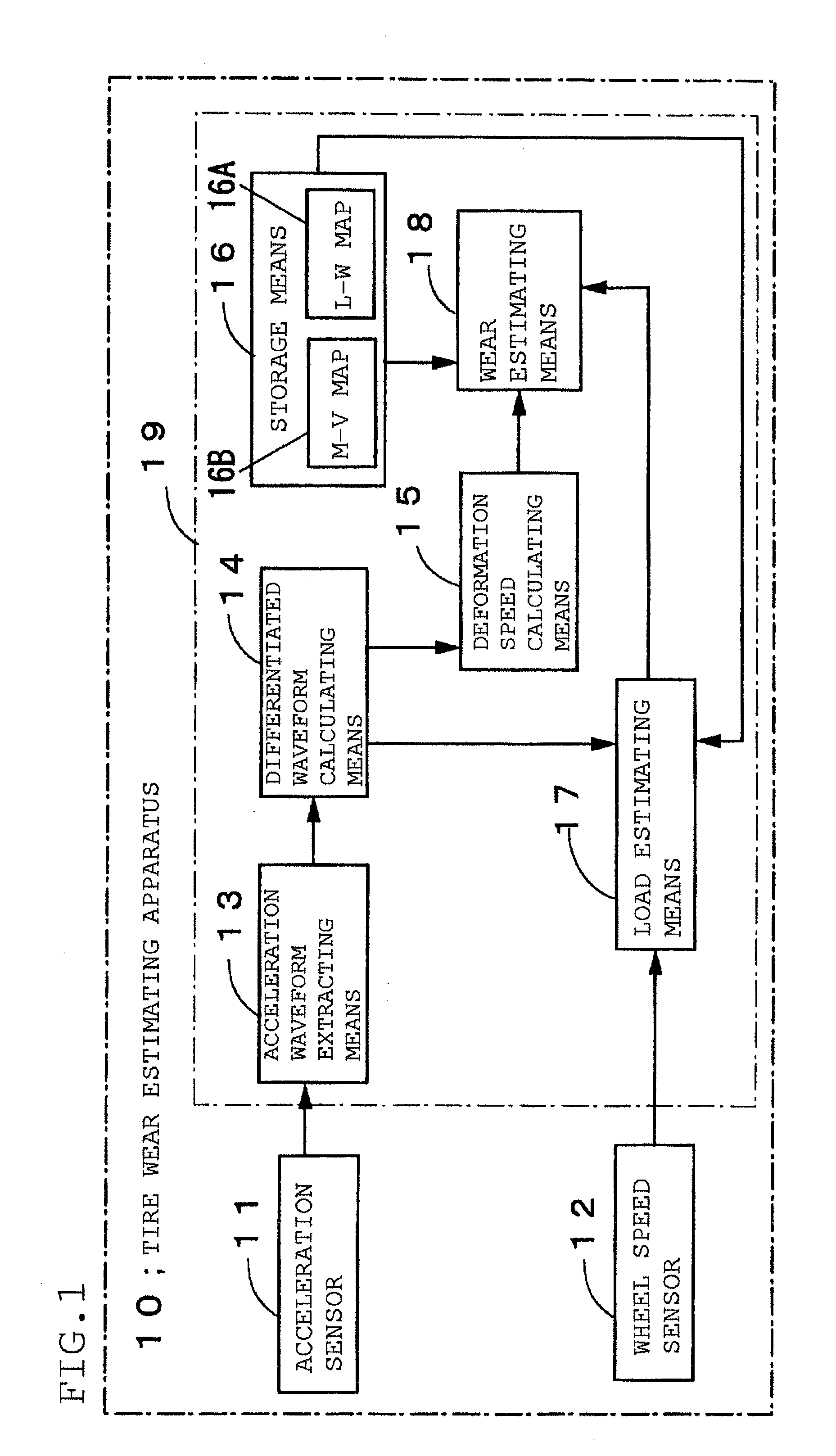
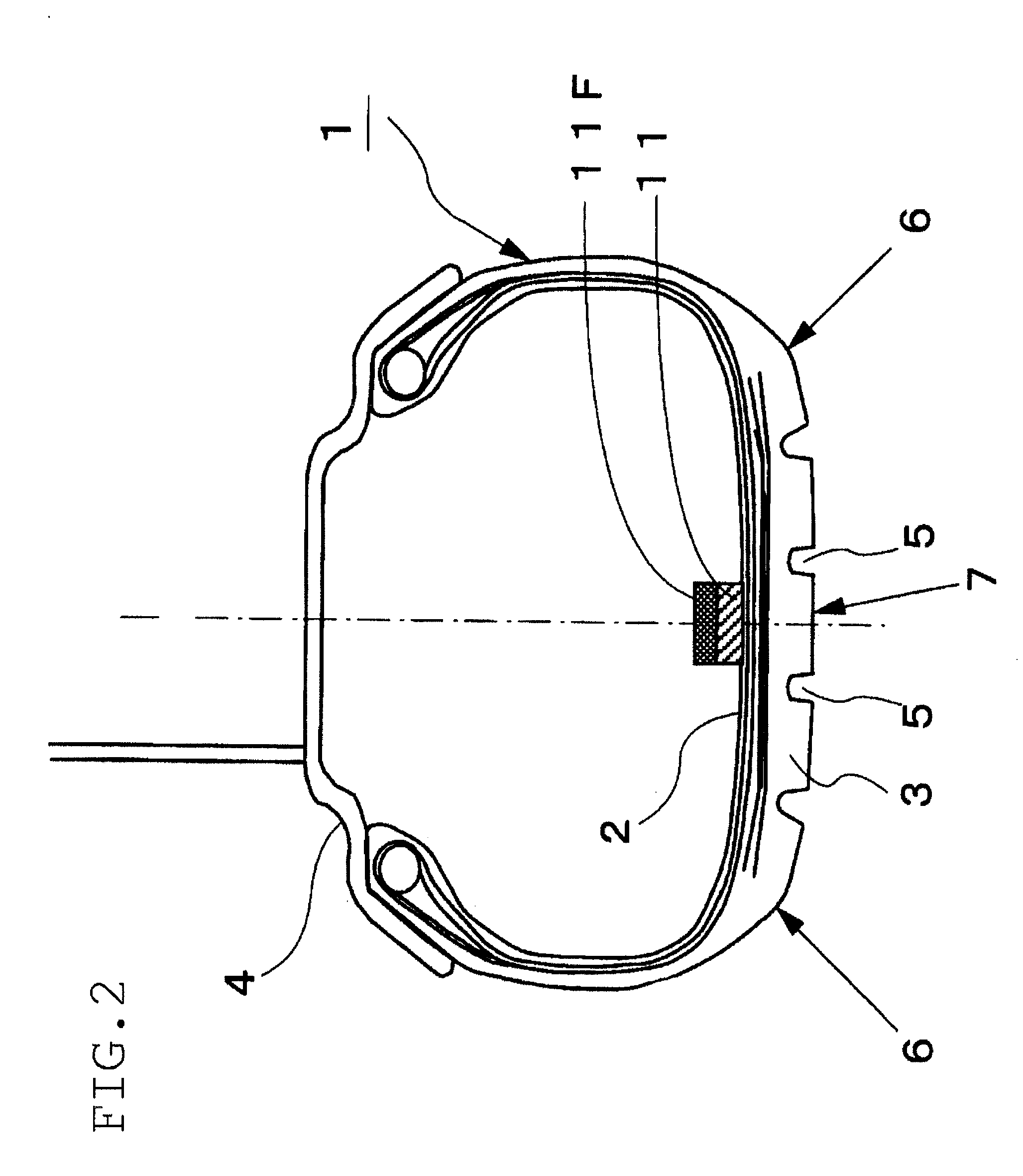
[0094]FIG. 1 is a functional block diagram showing a structure of a tire wear estimating apparatus 10 according to Embodiment 1 of the present invention. In the figure, reference numeral 11 denotes an acceleration sensor for detecting the acceleration of the tire tread, 12 a wheel speed sensor for detecting the rotational speed of a wheel, 13 an acceleration waveform extracting means for extracting a time-series waveform of the acceleration of the tire tread from the output of the acceleration sensor, 14 a differentiated waveform calculating means for calculating a differentiated waveform of acceleration which is a time-series waveform of values of differentiated acceleration, 15 a deformation speed calculating means for calculating the level of a leading edge side peak, which is the former of the two peaks appearing in the differentiated waveform of acceleration, and outputting the calculated level of the leading edge peak, 16 a storage means 16 for storing a predetermined L-W map ...

embodiment 2

[0131]In Embodiment 1 heretofore described, the degree of wear of a tire is estimated by calculating the index V of deformation speed at the contact edge portion of the tire tread from a differentiated waveform of the radial acceleration of the tire detected by an acceleration sensor 11. However, it is also possible to estimate the degree of tire wear by calculating the index Y of the amount of deformation in the radial direction of the tire at the bulge point of the tread from the radial acceleration waveform of the tire.

[0132]FIG. 10 is a diagram comparing radial acceleration waveforms of the tire tread of summer tires. The tires of 205 / 65R15 size were run on a flat-belt testing machine under the conditions of a speed of 40 km / h, a load of 5 kN, and an internal pressure of 230 kPa. The horizontal axis represents time (sec), and the vertical axis the magnitude (G) of acceleration in the radial direction of the tire. In the figure, the solid line represents the data of a new tire, w...

embodiment 3

[0139]FIG. 12 is a functional block diagram showing a structure of a tire wear estimating apparatus 30 according to Embodiment 3 of the present invention. In the figure, reference numeral 11 denotes an acceleration sensor, 32 an acceleration differentiated waveform calculating means, 33 a deformation speed calculating means, 34 a rotation time calculating means, 35 a contact time calculating means, 36 a contact time ratio calculating means, 37 a standardized deformation speed index calculating means, 38 a storage means, and 39 a tire wear estimating means.

[0140]In the same way as in Embodiment 1 and Embodiment 2, the acceleration sensor 11 detects the acceleration of the inner surface of the tire tread. And this acceleration sensor 11 constitutes a sensor section 30A of the tire wear estimating apparatus 30 according to the present invention, and the component means from the acceleration differentiated waveform calculating means 32 to the wear estimating means 39 constitute a calcul...


PUM


Abstract

The degree of wear of a tire is estimated with constant accuracy. An acceleration sensor (11) is installed on the inner surface in the inner liner region of a tire to detect the acceleration of the tread in the radial direction of the tire. The peak level on the leading edge side or the trailing edge side of the tread appearing in the differentiated waveform of the detected acceleration is calculated and used as an index V of deformation speed of the tread. The degree of wear of the tire is estimated on the basis of the calculated index V of deformation speed and an M-V map (16B) showing a predetermined relationship between the degree M of tire wear and the index V of deformation speed.

Description

TECHNICAL FIELD[0001]The present invention relates to a method for estimating the degree of wear of a tire.BACKGROUND ART[0002]Generally tire wear leads to lowered draining performance and longer braking distance on wet road surfaces. Also, in the case of winter tires, wear can bring about a marked drop in grip performance on an icy or snow-covered road. Furthermore, excessive wear can be very dangerous by allowing water to seep into the tread belts, which can eventually cause a rupture of the tire. Small vehicles are so arranged that when the remaining groove depth of a tire is reduced to 1.6 mm, a rubber projection called a “slip sign” makes its appearance in the tire groove. To ensure running safety of a vehicle, tires should be replaced before the appearance of the slip sign, but there are, in fact, many drivers who are least interested in such maintenance practice.[0003]Thus, there is demand for technologies for automatically detecting wear of tires to give a warning to the dri...

Claims


Application Information

Patent Timeline
Patent Type & Authority Applications(United States)
IPC IPC(8): G01M17/02
CPCB60C11/24G01M17/02B60C11/246B60C11/243
Inventor MORINAGA, HIROSHI
Owner BRIDGESTONE CORP
Why Eureka
Try Eureka