Ship rudder and ship provided therewith

a technology for rudder blades and ships, applied in the direction of steering components, floating buildings, bilge keels, etc., can solve the problems of more severe environmental pollution and high fuel consumption, and achieve the effect of improving afflux flow and efficiency

Active Publication Date: 2010-07-29
WOBBEN ALOYS
View PDF11 Cites 4 Cited by
  • Summary
  • Abstract
  • Description
  • Claims
  • Application Information

AI Technical Summary

Benefits of technology

[0008]The rudder blade is twisted in itself, wherein the twisting is adapted to the configuration of the flow of the water at the stern of the ship, that is to say in the region of the mounting location of the rudder blade. In this respect, the rudder blade is

Problems solved by technology

That flow resistance signifies higher fuel consumption and thus a higher level of environmental pollution or with the same fuel consumption or t

Method used


Image

  • Ship rudder and ship provided therewith
  • Ship rudder and ship provided therewith
  • Ship rudder and ship provided therewith

Examples


Embodiment Construction

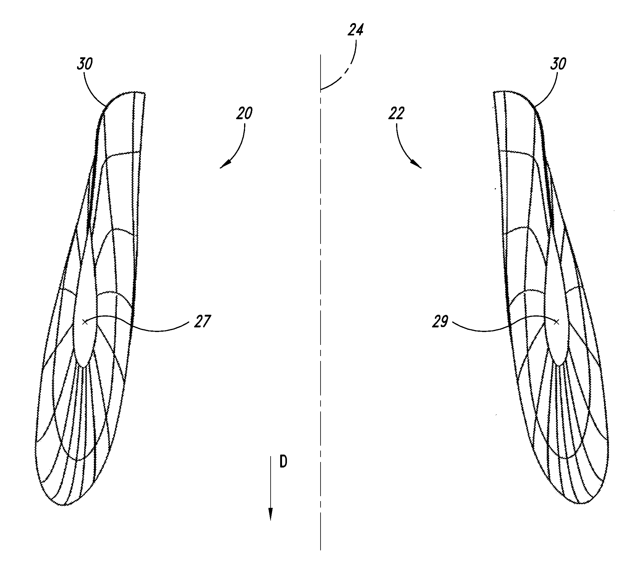
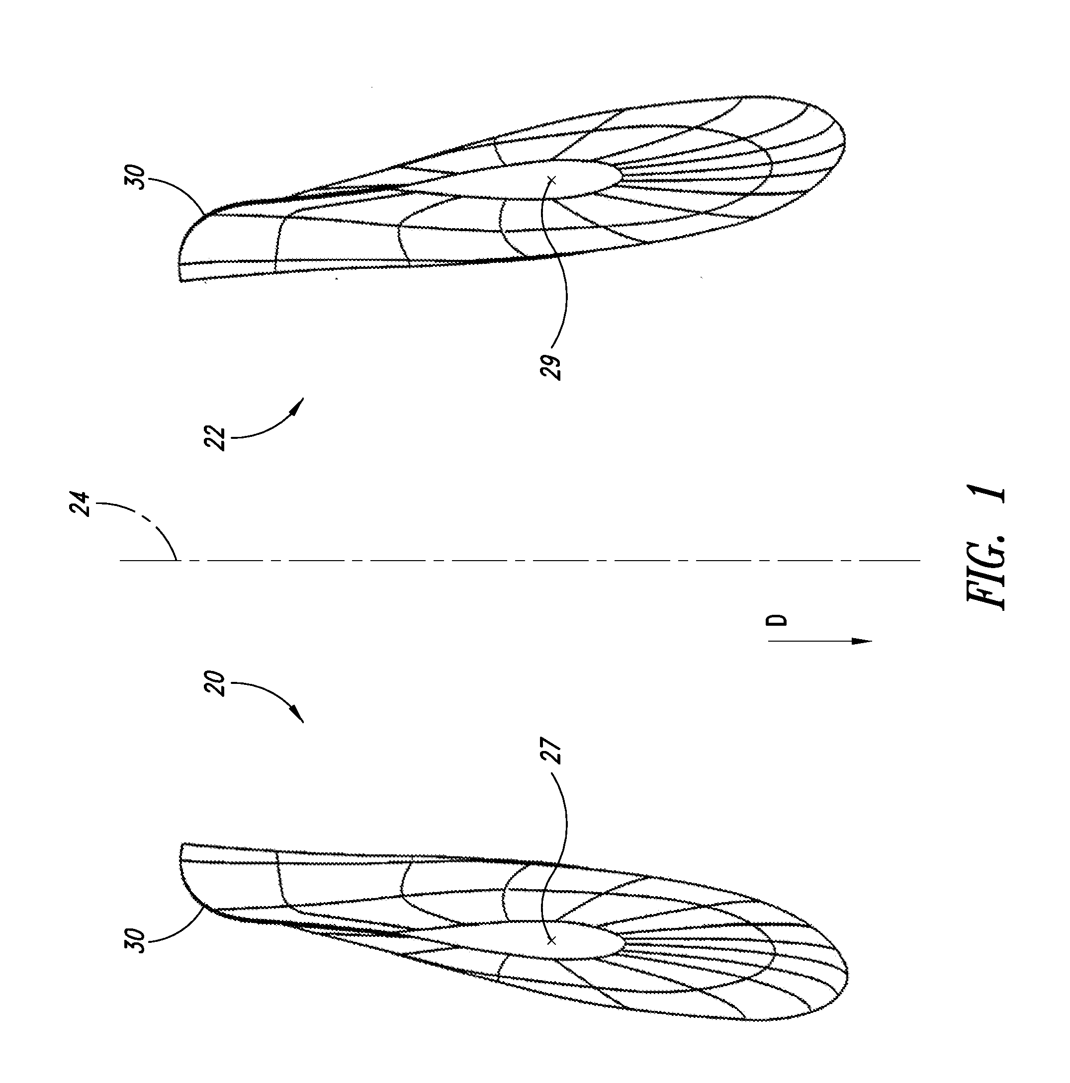
[0015]FIG. 1 shows two rudder blades 20, 22 from the perspective of looking up from below a ship 10 (shown in FIG. 3) such that a keel line 24 of the ship 10 would be seen between the rudder blades 20, 22. There is a twist at the trailing edge 30 of the rudder blades 20, 22 as shown in this figure.

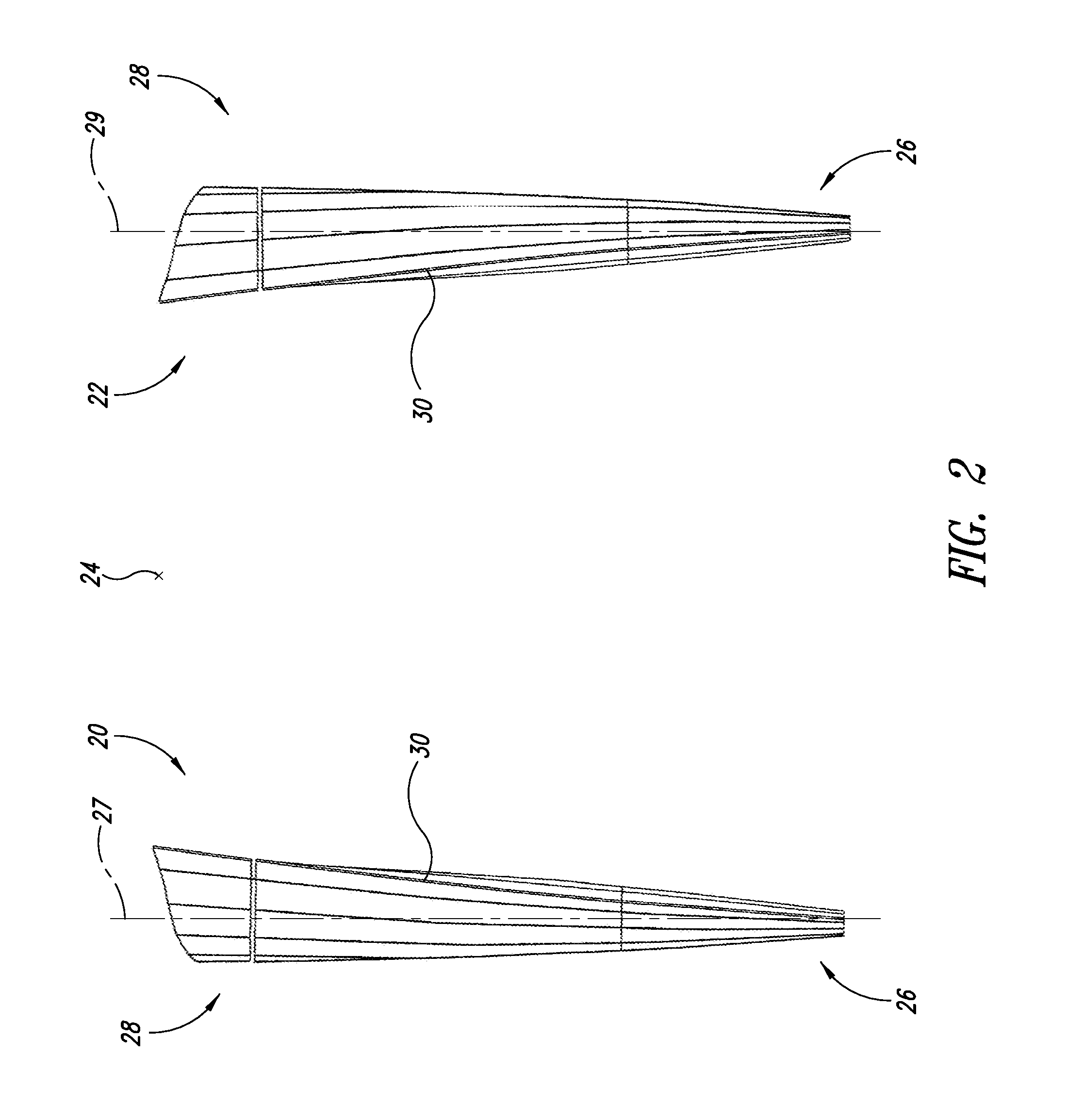
[0016]FIG. 2 shows two rudder blades 20, 22 from the perspective of looking at the stern of a ship 10 (shown in FIG. 3) from behind the ship 10. The twist present in the trailing edge 30 is shown. The trailing edge 30 also rotates as it extends from a lower region 26 to an upper region 28. Both rudder blades 20, 22 have the twist in a direction that is toward the center keel line 24 of the ship 10. Each rudder blade has a longitudinal axis 27, 29 respectively.

[0017]FIG. 3 shows a perspective view of a stern of a ship 10, the ship 10 having two rudder blades 20, 22. The port (left) rudder blade 20 is twisted towards the right, that is to say towards the keel line 24, while the starboard (ri...


PUM


Abstract

A twisted rudder blade for a ship having a twist that is adapted to the configuration of the flow of the water in the region of the rudder blade if no propeller in operation is disposed in front of the rudder blades in the direction of travel of the ship.

Description

BACKGROUND[0001]1. Technical Field[0002]The present invention concerns a rudder blade for a ship and a ship having at least one rudder blade according to the invention.[0003]2. Description of the Related Art[0004]If the flow along the hull of a ship as it moves is considered, it can then be clearly seen that, at a tapering stern of the ship, the flow does not extend exactly parallel to the line of the keel of the ship but follows the configuration of the stern of the ship.[0005]A rudder of conventional design, that is to say expressed in simple terms a flat plate, which is mounted laterally displaced from the line of the keel in the stern region of the ship and is oriented in the zero-degree position exactly parallel to the line of the keel would therefore have an afflux flow thereagainst at an inclined angle and thus gives rise to a flow resistance. That flow resistance signifies higher fuel consumption and thus a higher level of environmental pollution or with the same fuel consum...

Claims


Application Information

Patent Timeline
IPC IPC(8): B63H25/38B63H9/02
CPCB63H25/38B63H2025/388B63H2025/066
Inventor WOBBEN, ALOYSROHDEN, ROLFHOLTKAMP, DIRK
Owner WOBBEN ALOYS
Why Eureka
Try Eureka