

Universal cell frame for high-pressure water electrolyzer and electrolyzer including the same
a technology of high-pressure water electrolyzers and cell frames, which is applied in the field of water electrolyzers, can solve the problems of high pressure drop in the frame porting region of the coolant loop, and achieve the effect of reducing scrap (and cost) and facilitating stack assembly
- Summary
- Abstract
- Description
- Claims
- Application Information
AI Technical Summary
Benefits of technology
Problems solved by technology
Method used
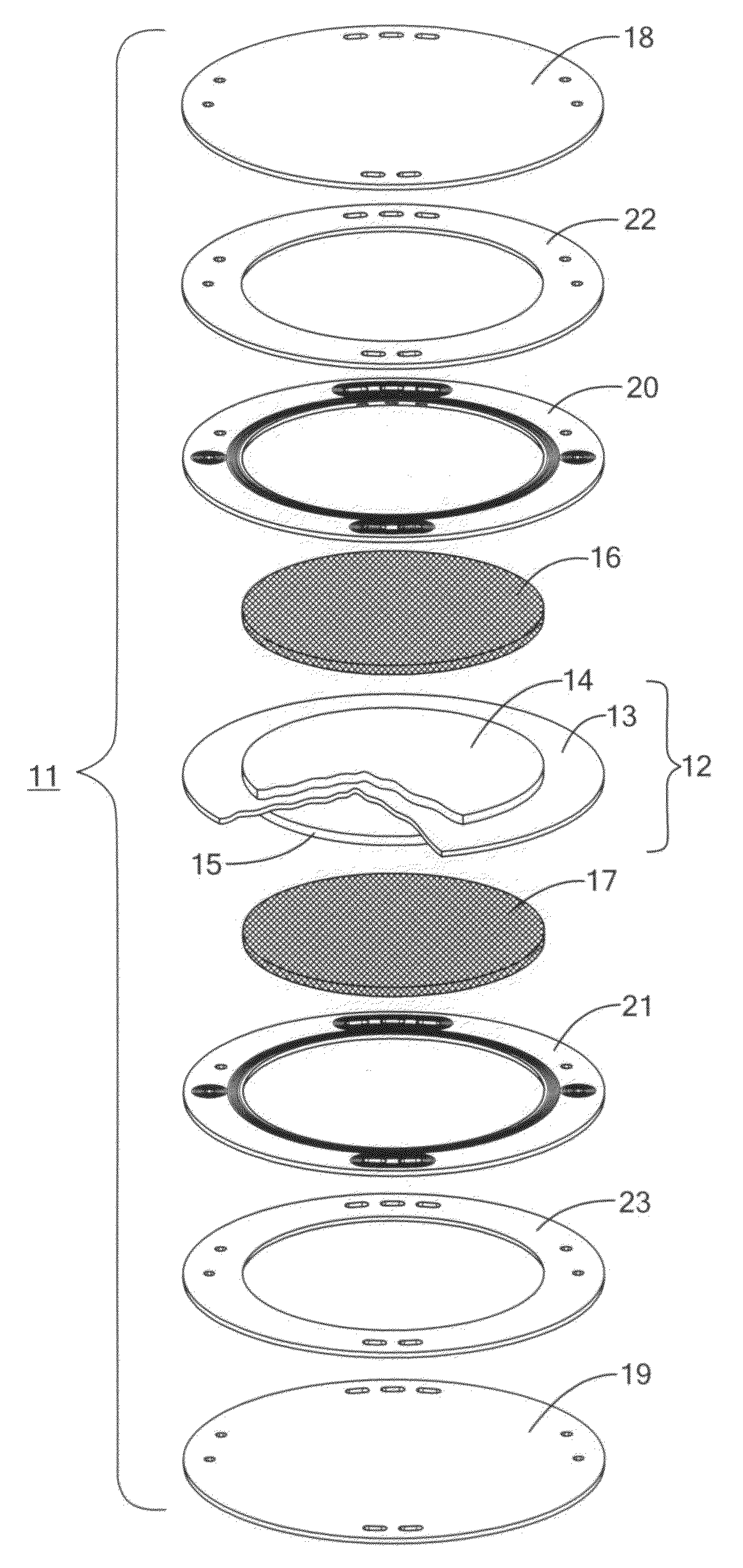
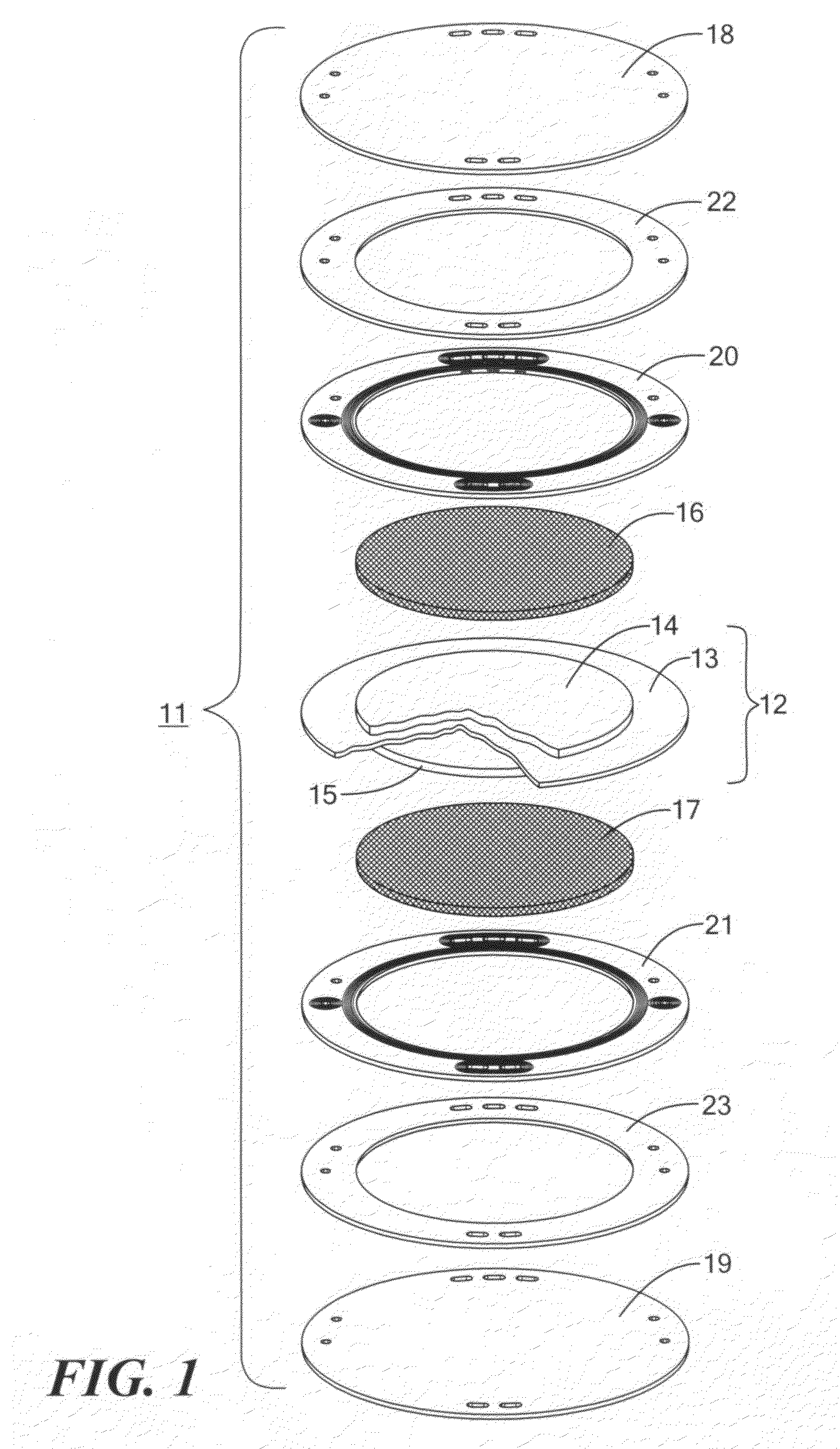
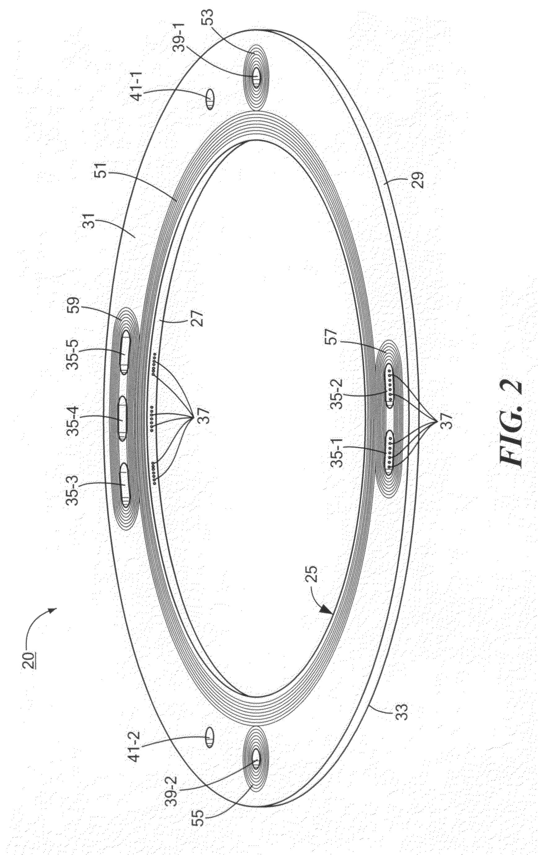
Image

Examples
example 1
Proof-of Concept Testing in Two-Part Welded Frame, Electrolyzer Cell
[0059]Testing was conducted on a two-part ultrasonically welded frame that featured four symmetric clusters of three axial through slots that characterize the universal frame. Axial porting and the symmetric clusters of uniform slots performed well on the anode, low-pressure side of the cell when electrochemically tested in an electrolysis cell with an active cell area of 160 cm2 at 60 psi, 700 mA / cm2.
example 2
Durability Testing in an Electrolyzer Short Stack under Cathode Feed Conditions
[0060]A three-cell short stack with an active cell area of 160 cm2 / cell was built with universal frames on both the anode and cathode sides of the cells, NAFION N117 membranes and plumbed for cathode feed operation. The stack ran successfully for over 500 hours. Testing was performed at 80° C., 1200 psi balanced pressure (1200 psi Oxygen and Hydrogen), and a current density of 700 mA / cm2 with a cell voltage of 1.683.
example 3
Durability Testing in an Electrolyzer Short Stack under Anode Feed Conditions
[0061]A three-cell short stack with an active cell area of 160 cm2 / cell was built with universal frames on the anode and cathode sides, NAFION N117 membranes and plumbed for anode feed operation. The stack ran successfully for over 500 hours. Testing was performed at 80° C., 1200 psi balanced pressure (1200 psi Oxygen and Hydrogen), and a current density of 700 mA / cm2 with a cell voltage of 1.654.
PUM
| Property | Measurement | Unit |
|---|---|---|
| pressure | aaaaa | aaaaa |
| differential pressures | aaaaa | aaaaa |
| area | aaaaa | aaaaa |
Abstract
Description
Claims
Application Information