Acoustic wave device

a technology of acoustic waves and electrodes, applied in piezoelectric/electrostrictive/magnetostrictive devices, piezoelectric/electrostrictive/magnetostrictive machines, piezoelectric/electrostrictive/magnetostrictive devices, etc., can solve the problem of large spurious response of higher order mode, increase the absolute value of the frequency-temperature coefficient tcf of the boundary acoustic wav

Active Publication Date: 2010-07-29
MURATA MFG CO LTD
View PDF7 Cites 24 Cited by
  • Summary
  • Abstract
  • Description
  • Claims
  • Application Information

AI Technical Summary

Benefits of technology

[0024]In another preferred embodiment of the present invention, an acoustic wave device which includes an IDT electrode of an electrode film which is made of one of the metals selected from the group consisting of Au, Ag, Cu, Pt, Ta, W, Ni, Fe, Cr, Mo, Ti and an alloy including one of these metals as a main component, or laminated film with a second electrode film which is a different metal from the other metal films, for example, is preferably provided. In this case, the reflection coefficient of the IDT electrode is increased. Preferably, the laminate structure is provided with a plurality of electrode films made of Pt or Al or an alloy including one of these metals as a main component, for example. In this case, an IDT having high reliability and low resistivity is provided.
[00

Problems solved by technology

There is a problem in that a large spurious response of the higher order mode occurs.
However, there is a problem in that the absolute value of the frequenc

Method used


Image

  • Acoustic wave device
  • Acoustic wave device
  • Acoustic wave device

Examples


Embodiment Construction

[0053]Hereinafter, the present invention will be disclosed using the following preferred embodiments of the present invention with reference to the accompanying drawings.

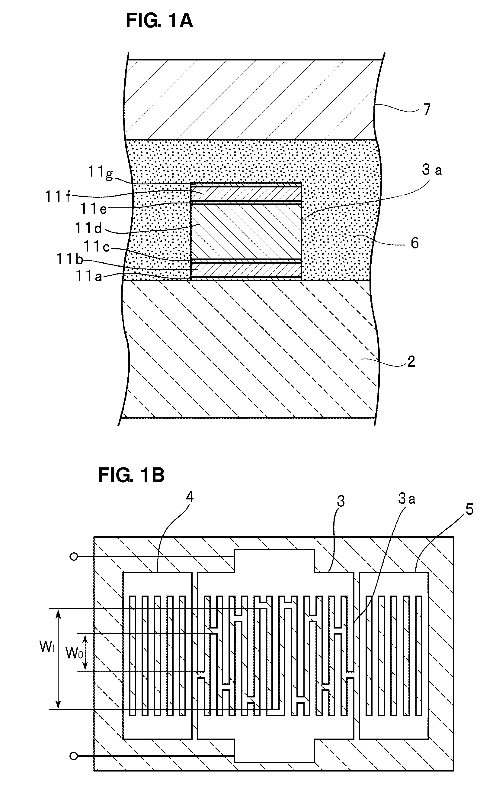
[0054]FIG. 1A is a schematic partial cutaway front cross-sectional view of a boundary acoustic wave device according to a preferred embodiment of the present invention and FIG. 1B is a schematic plan view showing an electrode structure thereof.

[0055]As shown in FIG. 1A, the boundary acoustic wave device includes a piezoelectric substrate 2 made of LiNbO3, for example. A SiO2 layer 6 is laminated on the piezoelectric substrate 2.

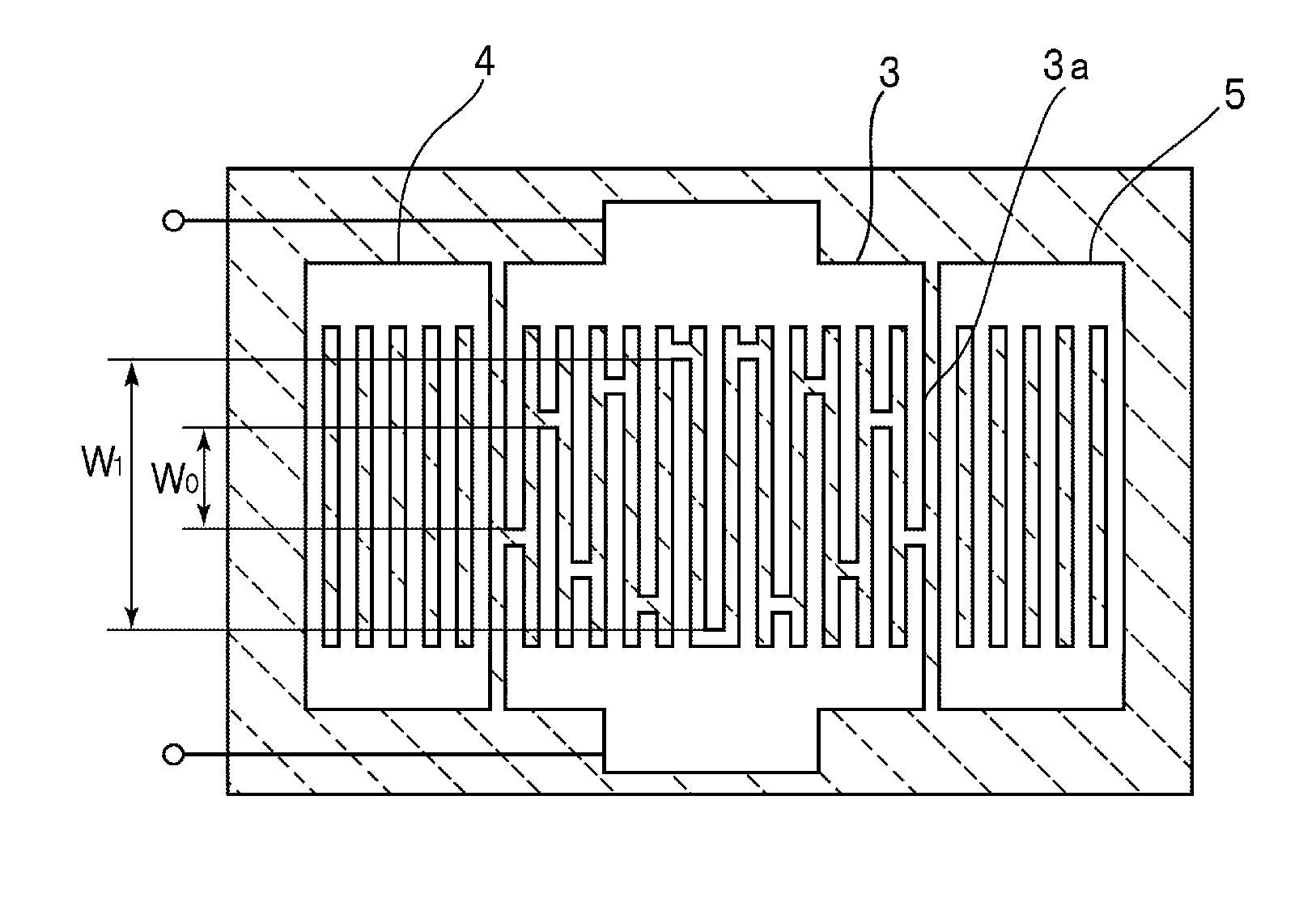
[0056]An IDT electrode 3 is disposed at the interface between the piezoelectric substrate 2 and the SiO2 layer 6. FIG. 1A shows a partial cutaway enlarged cross-sectional view of one finger of the IDT electrode 3. Practically, as shown in FIG. 1B, the IDT electrode 3 and reflectors 4 and 5 are disposed on the piezoelectric substrate 2, wherein the reflectors 5 and 6 are disposed at two sides ...


PUM


Abstract

An acoustic wave device having an improved frequency-temperature characteristic and in which a spurious response of the higher order mode is suppressed includes a piezoelectric substrate made of LiNbO3, a SiO2 layer laminated on the piezoelectric substrate, and an IDT electrode disposed in an interface of the piezoelectric substrate and the SiO2 layer, wherein φ and θ of Euler angles expressed by (φ, θ, ψ) of LiNbO3 substrate satisfy φ=0° and 80°≦θ≦130°, respectively. The acoustic wave device using an acoustic wave primarily having an SH wave, wherein ψ is set to satisfy 5°≦ψ≦30°.

Description

BACKGROUND OF THE INVENTION[0001]1. Field of the Invention[0002]The present invention relates to an acoustic wave device for use as a bandpass filter, a resonator, or other suitable devices, and more particularly, to an acoustic wave device including a dielectric layer, such as SiO2, that is laminated on a piezoelectric substrate composed of LiNbO3.[0003]2. Description of the Related Art[0004]Heretofore, acoustic wave devices, such as surface acoustic wave devices and boundary acoustic wave devices, have been used for bandpass filters, for example, in communication equipment.[0005]One example of a boundary acoustic wave device is disclosed in International Publication No. WO98 / 52279. FIG. 24 is a plan view and FIG. 25 is a partially enlarged front cross-sectional view that shows a relevant portion of a boundary acoustic wave device disclosed therein.[0006]The boundary acoustic wave device 1001 includes a LiNbO3 substrate 1002. An IDT electrode 1003 is disposed on the substrate 1002....

Claims


Application Information

Patent Timeline
IPC IPC(8): H01L41/04H01L41/047H01L41/08
CPCH03H9/0222H03H9/02559H03H9/131H03H9/02834H03H9/02669H03H9/14541
Inventor MIMURA, MASAKAZU
Owner MURATA MFG CO LTD
Why Eureka
Try Eureka