
Image outputting system, image outputting method, and image outputting program

a technology of image outputting and image, applied in the field of image outputting system, image outputting method, image outputting program, can solve the problems of difficult to realize small meshes, misalignment between images at a joint portion, etc., and achieve the effect of easy provision of images

Inactive Publication Date: 2010-07-29
HAMAMATSU PHOTONICS KK
View PDF14 Cites 7 Cited by
  • Summary
  • Abstract
  • Description
  • Claims
  • Application Information

AI Technical Summary

Benefits of technology

[0006]The present invention has been made to solve such problems and an object thereof is to provide an image outputting system, an image outputting method, and an image outputting program for easily providing an image which is in focus at any position in the image to be an observation target of a user and is free from misalignment in the image in a virtual microscope or the like.
[0020]Therefore, an image which is focused in the area can be output. Moreover, according to the present invention, images are not put together to match focal points in one image and therefore an image without misalignment can be output. That is, according to the present invention, it becomes possible to easily provide an image which is focused at any point in the image which is to be an observation target by the user and is free from misalignment in the image.

Problems solved by technology

Even if the mesh is divided smaller, there is a limit to make a visual field of a high objective lens finer and therefore it is difficult to realize smaller meshes.
Furthermore, since images with different focal positions are put together, there may be misalignment between images at a joint portion.

Method used


Image

  • Image outputting system, image outputting method, and image outputting program
  • Image outputting system, image outputting method, and image outputting program
  • Image outputting system, image outputting method, and image outputting program

Examples


Embodiment Construction

[0033]Hereinafter, preferred embodiments of the image outputting system and the image outputting method according to the present invention will be explained in detail with reference to the drawings. Here, the same reference numerals are given to the same components and redundant explanation thereof is omitted.

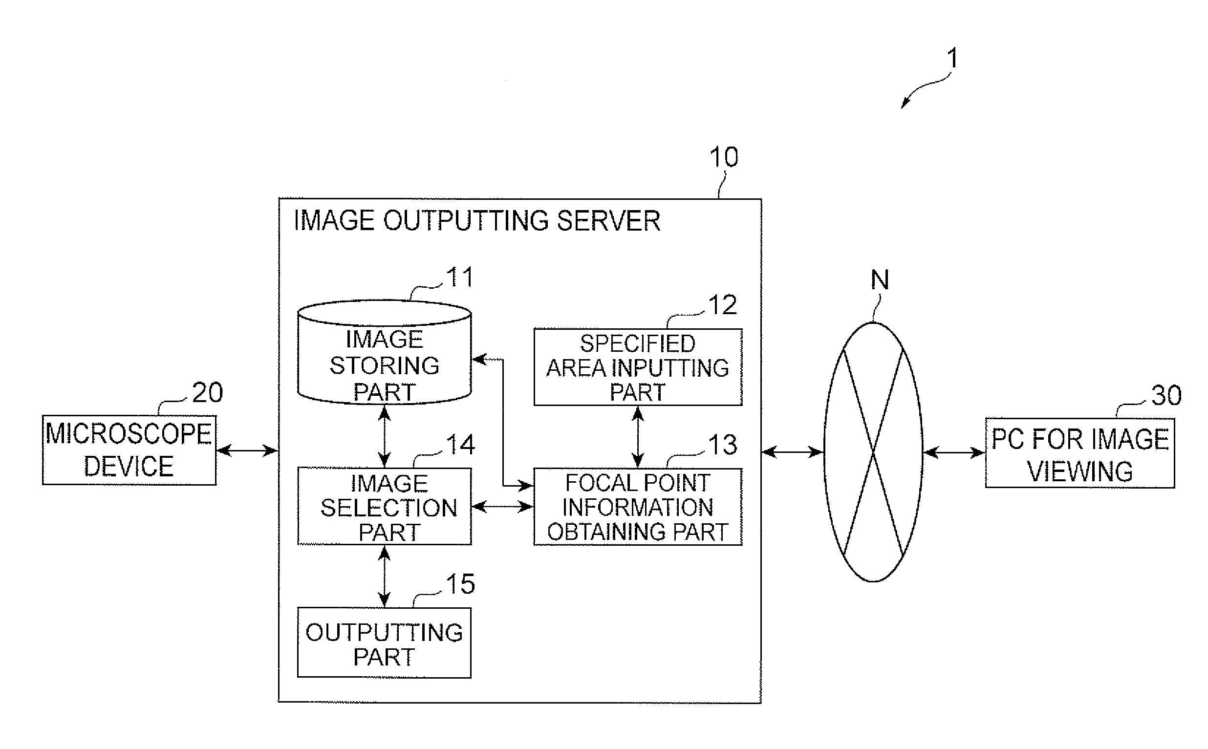
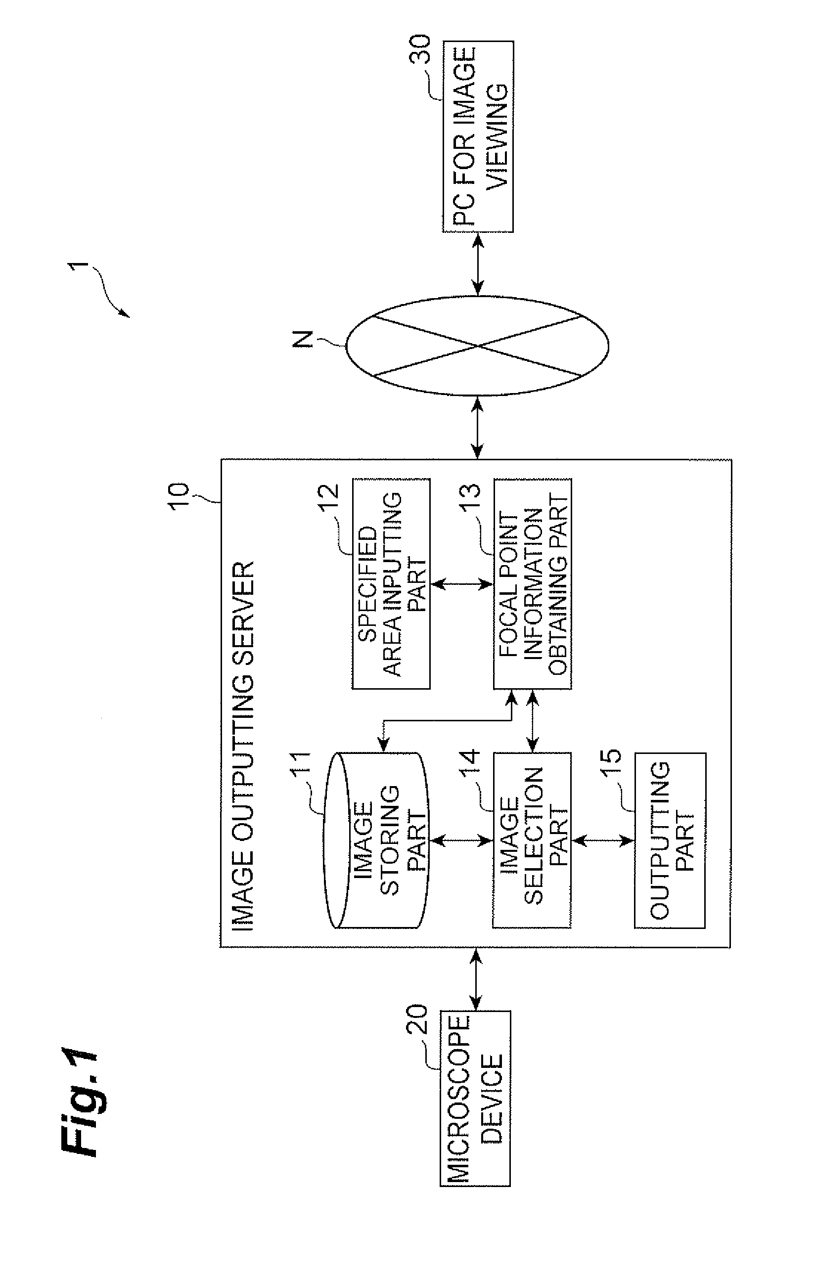
[0034]FIG. 1 shows configuration of an image outputting system 1 according to the present embodiment. The image outputting system 1 includes an image outputting server 10. Moreover, the image outputting system 1 may include a microscope device 20 and a personal computer (PC) for image viewing 30. The image outputting system 1 causes the image outputting server 10 to store data of an image (image data) taken by the microscope device 20 and outputs the image data from the image outputting server 10 in response to a request from a user (e.g., the PC for image viewing 30). Specifically, the image outputting system 1 is equivalent to a virtual microscope system.

[0035]As described ab...


PUM


Abstract

The present invention is aimed at easily providing an image which is in focus at any position in the image to be an observation target of a user and is free from misalignment in the image in a virtual microscope or the like.An image outputting server 10 includes an image storing part 11 for storing a plurality of image data with different focal points taken in an imaging direction which are images of a predetermined imaging target, specified area inputting means 12 for inputting information specifying an area in the image data, focal point information obtaining means 13 for obtaining information indicating the matching degree of a focal point in a specified area of each of the plurality of image data, image selection means 14 for selecting an image data to be output from the plurality of image data on the basis of the matching degree of the focal point, and outputting means 15 for outputting the thus selected image data.

Description

BACKGROUND OF THE INVENTION[0001]1. Field of the Invention[0002]The present invention relates to an image outputting system, an image outputting method, and an image outputting program for outputting an image used for a virtual microscope or the like.[0003]2. Related Background Art[0004]In recent years, a virtual microscope which enables observation on a display by converting an image taken by an optical microscope into digital data has been used in the field of pathology or the like. According to the Japanese Published Unexamined Patent Application No. 2005-37902 (Patent Document 1), an area to be a target of imaging is divided into a plurality of meshes and a plurality of images of each mesh are taken with different focal positions (focal distance) in an imaging direction. Then, only image parts of the thus taken images which are in focus are put together to obtain an image used for the virtual microscope. Every mesh of the thus obtained image is in focus.SUMMARY OF THE INVENTION[...

Claims


Application Information

Patent Timeline
Patent Type & Authority Applications(United States)
IPC IPC(8): G09G5/00
CPCG02B21/367G06T2207/10056G06T5/50
Inventor COOKE, JEREMYUCHIYAMA, SHIGERUOSHIRO, MASAFUMI
Owner HAMAMATSU PHOTONICS KK
Learn More