Suspension board with circuit

a suspension board and circuit technology, applied in the direction of maintaining the head carrier alignment, recording information storage, instruments, etc., can solve the problems of affecting the layout design of the suspension board, the inability to compactly mount the suspension board with circuit in the hard disk drive, and the short circuit easily occurring therebetween

Inactive Publication Date: 2010-07-29
NITTO DENKO CORP
View PDF24 Cites 22 Cited by
  • Summary
  • Abstract
  • Description
  • Claims
  • Application Information

AI Technical Summary

Benefits of technology

[0025]Therefore, in the suspension board with circuit, the folded-back state of the auxiliary portion with respect to the substrate main body portion can be stabilized with a simple structure.

Problems solved by technology

As a result, the element-side terminal portion and the head-side connection terminal portion should be arranged at a high density, leading to a problem that a short circuit easily occurs therebetween.
However, this results in a problem that the suspension board with circuit cannot be compactly mounted in a hard disk drive.
There is also a problem that, since the light emitting element and the slider are both mounted on the same surface of the metal supporting board, a restriction associated with layout design arises.

Method used


Image

  • Suspension board with circuit
  • Suspension board with circuit
  • Suspension board with circuit

Examples


Embodiment Construction

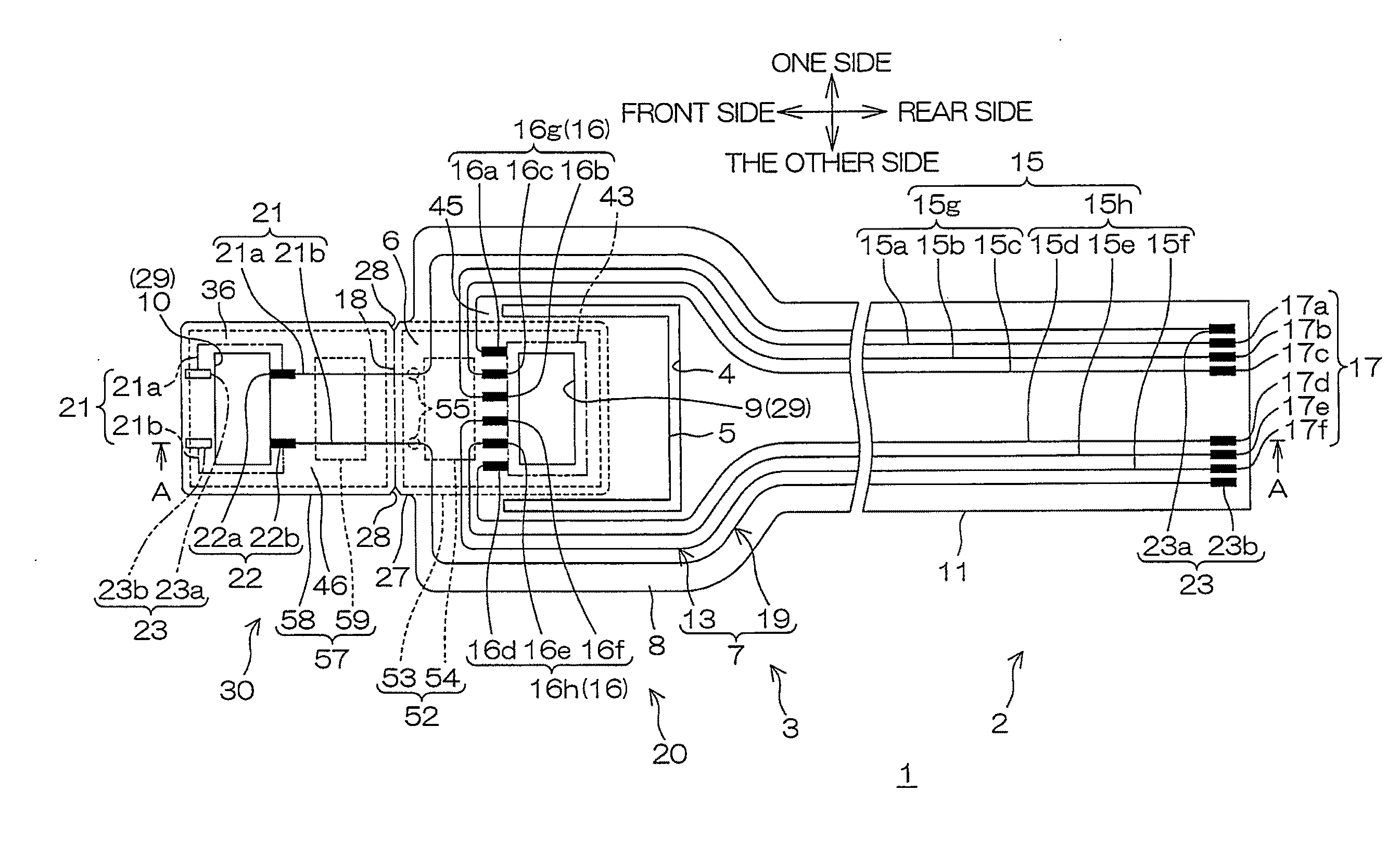
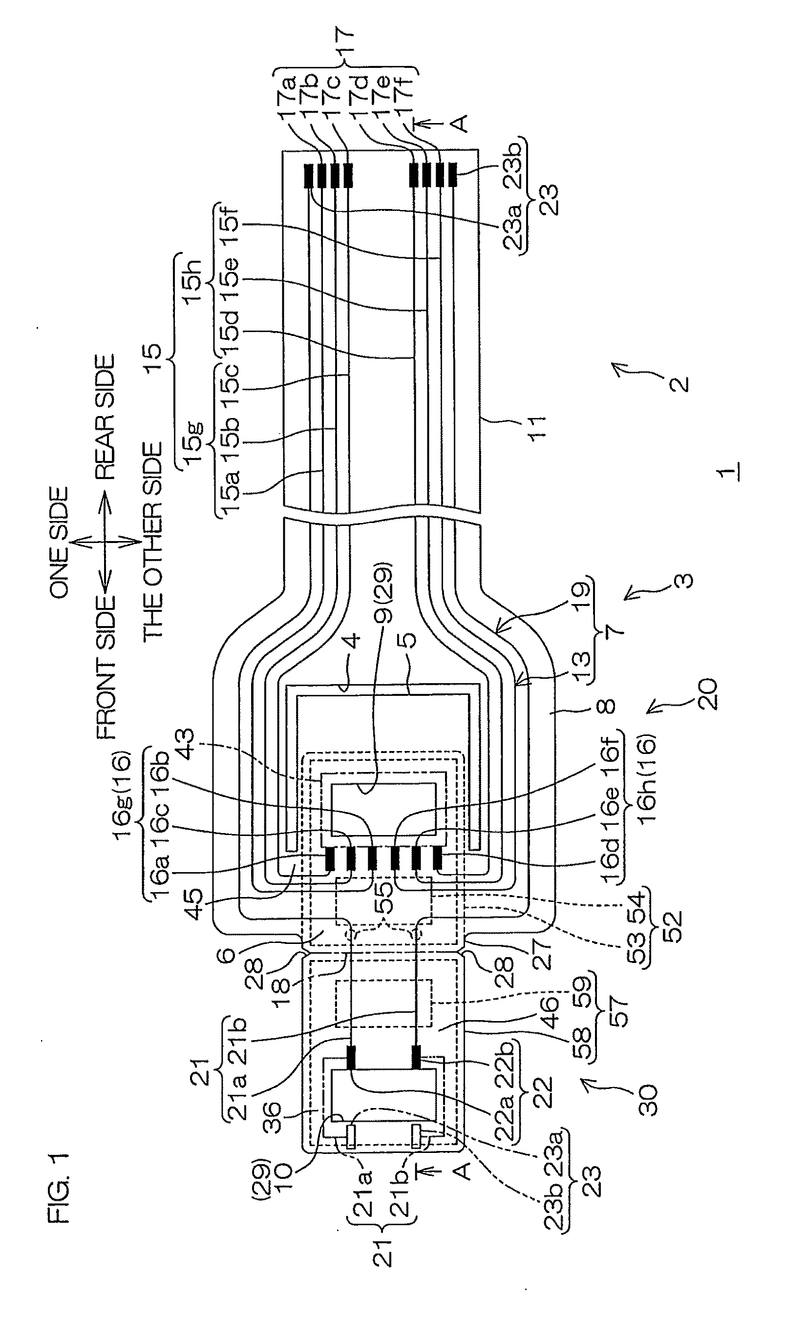
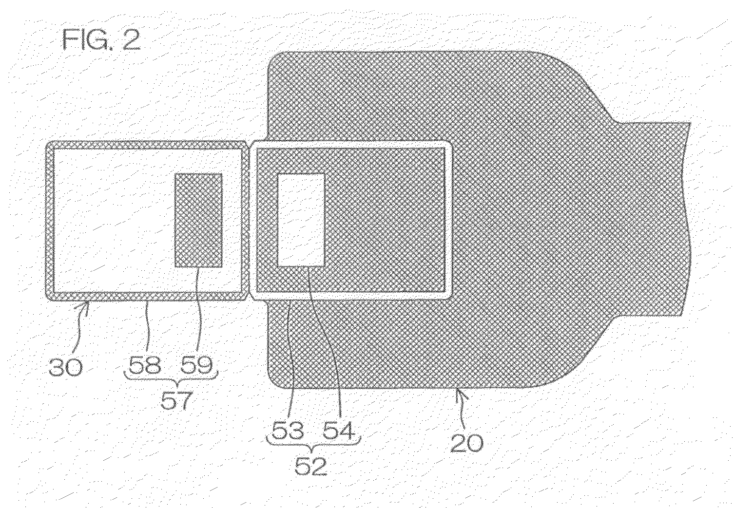
[0043]FIG. 1 is a plan view of a suspension board with circuit according to an embodiment of the present invention prior to a folding-back step (described later). FIG. 2 is a schematic view of a principal portion of a metal supporting board of the suspension board with circuit shown in FIG. 1. FIG. 3 is a cross-sectional view of the suspension board with circuit shown in FIG. 1 along the line A-A. FIG. 4 is a process view for illustrating a producing method of the suspension board with circuit shown in FIG. 3. FIGS. 5 to 7 show the suspension board with circuit of FIG. 1 after the folding-back step, in which FIG. 5 is a plan view thereof, FIG. 6 is a bottom view thereof, and FIG. 7 is a cross-sectional view thereof along the line B-B of FIG. 5.

[0044]In FIGS. 1, 5, and 6, an insulating base layer 12 and an insulating cover layer 14, each described later, are omitted for clear illustration of relative positioning of a conductive pattern 7 described later.

[0045]As shown in FIG. 1, a su...


PUM

PropertyMeasurementUnit
thicknessaaaaaaaaaa
thicknessaaaaaaaaaa
widthsaaaaaaaaaa

Abstract

A suspension board with circuit includes a board main body portion, an auxiliary portion folded back with respect to the board main body portion, a slider disposed close to the board main body portion, and mounting thereon a magnetic head, and a light emitting element disposed close to the auxiliary portion. The conductive pattern includes a first conductive pattern including a first terminal, and a second terminal connected to the magnetic head, and a second conductive pattern including a third terminal and a fourth terminal connected to the light emitting element. The first, second and third terminals are disposed on the board main body portion. The fourth terminal is disposed on the auxiliary portion. The back surface of the board main body portion is formed with a main-body-side interfitting portion. A back surface of the auxiliary portion is formed with an auxiliary-portion-side interfitting portion.

Description

CROSS-REFERENCE TO RELATED APPLICATIONS[0001]This patent application claims the benefit of U.S. Provisional Application No. 61 / 202,251, filed on Feb. 20, 2009, and claims priority from Japanese Patent Application No. 2009-013515, filed on Jan. 23, 2009, the contents of which are herein incorporated by reference in their entirety.BACKGROUND OF THE INVENTION[0002]1. Field of the Invention[0003]The present invention relates to a suspension board with circuit and, more particularly, to a suspension board with circuit used in a hard disk drive in which an optically assisted method is employed.[0004]2. Description of the Related Art[0005]In recent years, it has been known to use a suspension board with circuit in a hard disk drive in which an optically assisted method is employed. The optically assisted method is a recording method in which, when information is to be recorded, light is emitted from a light emitting element toward a magnetic disk to irradiate and heat the magnetic disk, an...

Claims


Application Information

Patent Timeline
Patent Type & Authority Applications(United States)
IPC IPC(8): G11B5/48
CPCG11B5/486G11B5/4853
Inventor OHSAWA, TETSUYANAITO, TOSHIKI
Owner NITTO DENKO CORP
Why Eureka
Try Eureka