Method for controlling device by using brain wave and brain wave interface system

a brain wave and interface system technology, applied in the field of device manipulation interface technique, can solve the problems of increasing the prevalence of wearable devices such as head-mounted displays (hmds), reducing the size and weight, and so as to achieve the effect of reducing the burden of device wearing

Active Publication Date: 2010-07-29
PANASONIC CORP
View PDF13 Cites 55 Cited by
  • Summary
  • Abstract
  • Description
  • Claims
  • Application Information

AI Technical Summary

Benefits of technology

[0030]According to the present invention, by using a device having a plurality of electrodes at positions in contact with the user, including his or her face, an electroencephalogram interface system is constructed which operates with an accuracy similar to that of a conventional electroencephalogram interface system which is based on an electroencephalogram measurement at the parietal. Such a device may be a device which is to be worn in a relatively narrow range on the head of the user, e.g., an eyeglasses (goggles)-type HMD, on which electrodes corresponding to the face and ears of the user may be provided. This makes it unnecessary for the user to wear any electrodes at positions other than positions where the device comes in contact with the user, such that electrode wearing is accomplished simultaneously with the wearing of the HMD, whereby the burden of device wearing is reduced.

Problems solved by technology

In recent years, wearable devices such as head-mount displays (HMD) are gaining prevalence due to decreases in the size and weight of devices.
However, if the aforementioned physical manipulations are required when controlling a device whose main body has a small size and which is characterized to be handsfree, e.g., an HMD, the handsfree feature will be undermined, thus being ineffective.
Therefore, it would be a burden on the user to separately wear any electrode other than the HMD.

Method used


Image

  • Method for controlling device by using brain wave and brain wave interface system
  • Method for controlling device by using brain wave and brain wave interface system
  • Method for controlling device by using brain wave and brain wave interface system

Examples


embodiment 1

[0095]FIG. 7 is a construction diagram of an electroencephalogram interface system 1 according to the present embodiment. The electroencephalogram interface system 1 includes an ear electrode portion 11, facial electrode portions 12, an electroencephalogram characteristic extraction section 13, a determination section 14, and a determination criterion database (DB) 15. In FIG. 7, the user 10 is illustrated for ease of understanding.

[0096]FIG. 8 illustrates an Example of constructing the electroencephalogram interface system 1 in the form of an eyeglasses (goggles)-type head-mount display (HMD). Hereinafter, the HDM-type electroencephalogram interface system 1 shown in FIG. 8 will be described in detail.

[0097]The names of respective portions of the HMD-type electroencephalogram interface system 1 shown in FIG. 8 are similar to those of eyeglasses. Hereinafter, portions which hang on the ears of the user 10 to fix the HMD main body will be referred to as “endpiece portions”. Portions ...

embodiment 2

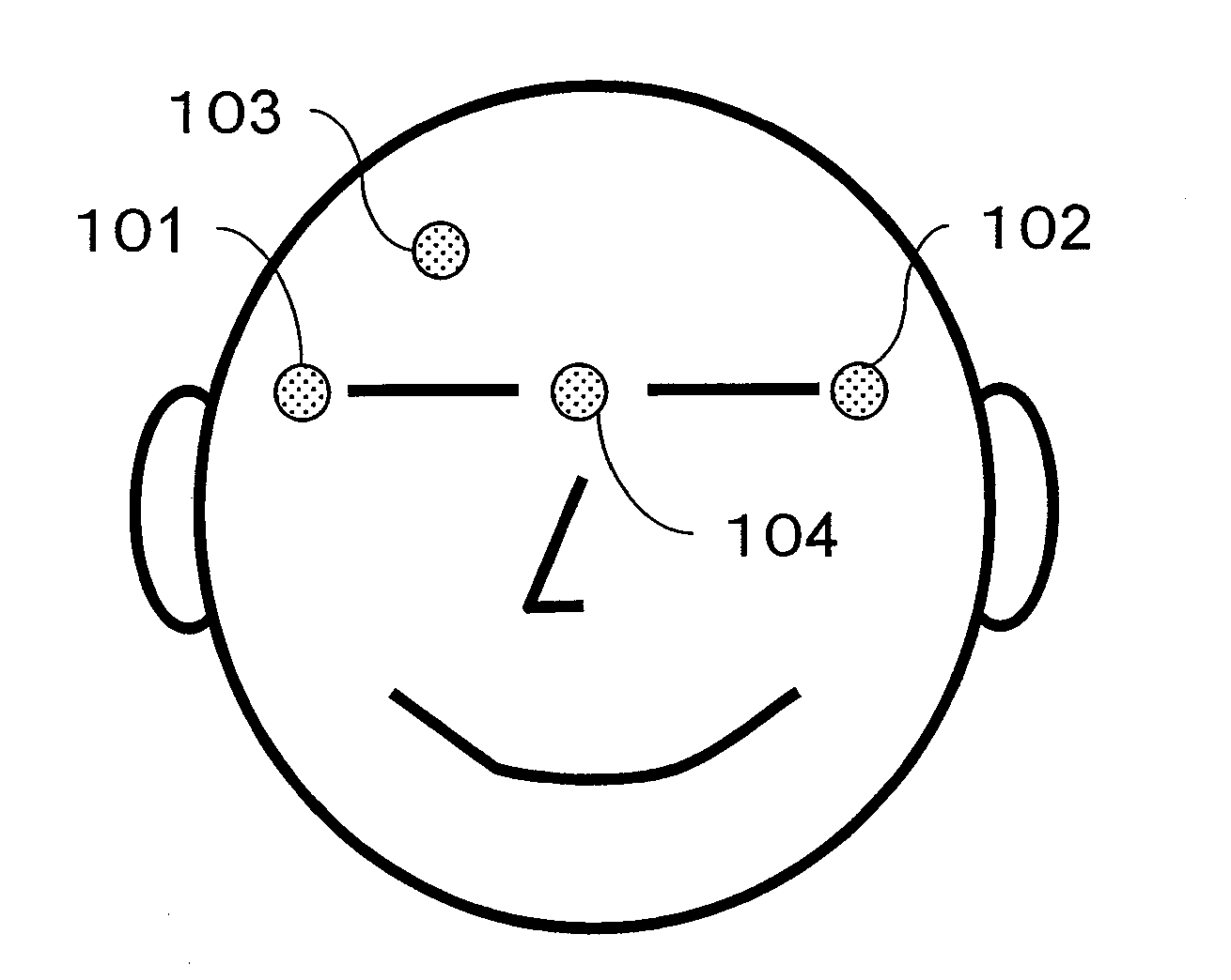
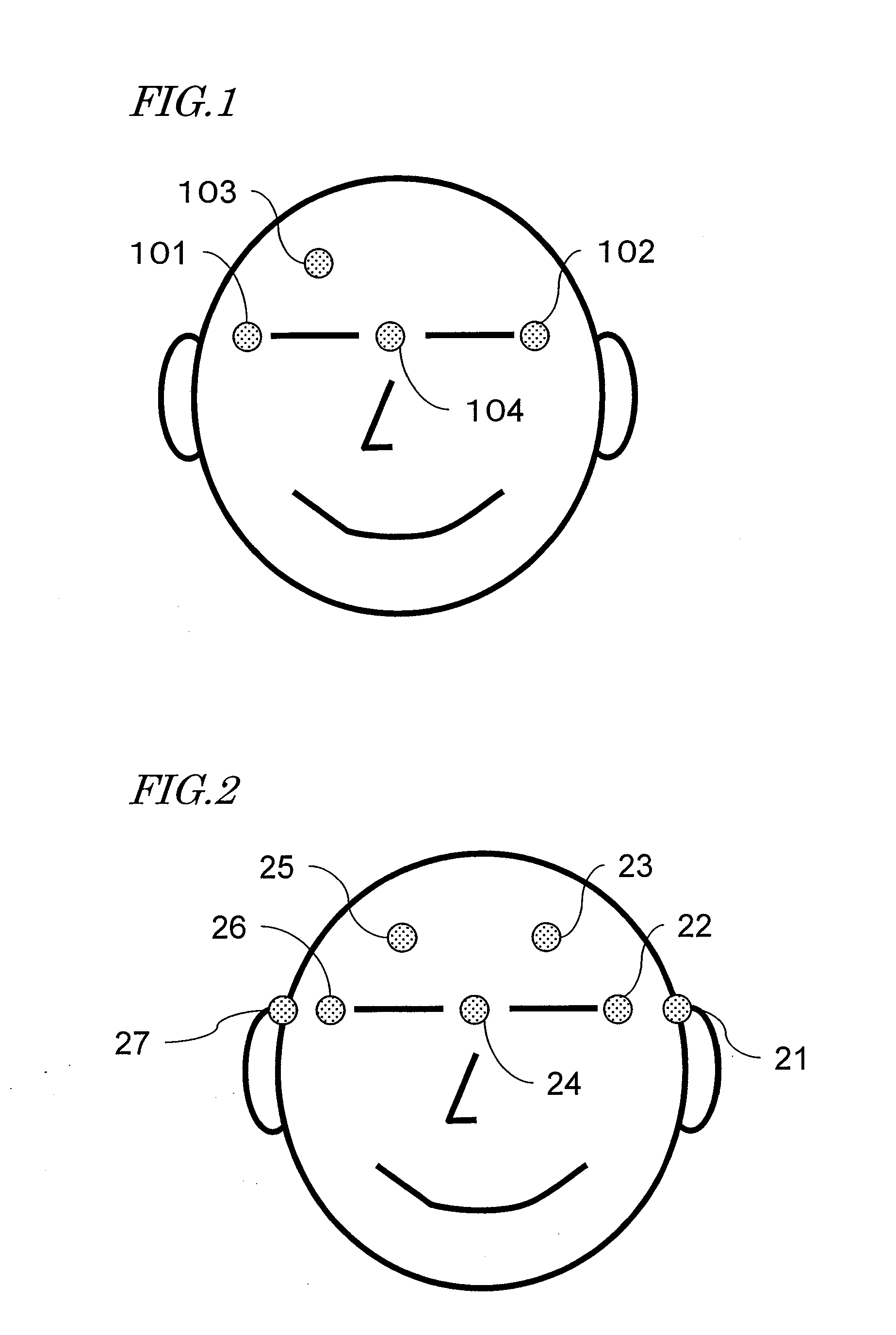
[0187]In Embodiment 1, determination is made by extracting electroencephalogram characteristic data from electroencephalograms obtained by using a reference electrode in an ear periphery and a plurality of electrodes at facial positions.

[0188]In the case of a device which cannot be stably worn, e.g., an HMD, it may often happen that the electrodes worn on the face become dislocated or detached, or that the reference electrode worn in an ear periphery become dislocated or detached. Moreover, it may often happen that contact between the electrodes and the skin become poor due to the skin state, which is susceptible to perspiration, the outside air temperature, and characteristics of each individual person such as dry skin, thus causing the electrodes to come off the skin. It may also often happen that impurities, e.g., sweat, come between the electrodes and the skin to cause an increased noise, such that electroencephalogram signals can no longer be correctly measured.

[0189]Thus, the ...


PUM


Abstract

The control method for a device includes steps of: presenting a visual stimulation concerning a manipulation menu for a device; measuring event-related potentials after the visual stimulation is presented, where event-related potentials based on a timing of presenting the visual stimulation as a starting point are measured from a potential difference between each of electrodes and at least one reference electrode respectively worn on a face and in an ear periphery of a user; from each of the measured event-related potentials, extracting electroencephalogram data which is at 5 Hz or less and contains a predetermined time section, and combining the extracted electroencephalogram data into electroencephalogram characteristic data; comparing the electroencephalogram characteristic data against reference data prepared in advance for determining a desire to select an item in the manipulation menu; and, based on a comparison result, executing a manipulation of the device corresponding to the item.

Description

[0001]This is a continuation of International Application No. PCT / JP2009 / 002968, with an international filing date of Jun. 26, 2009, which claims priority of Japanese Patent Application No. 2008-181645, filed on Jul. 11, 2008, the contents of which are hereby incorporated by reference.BACKGROUND OF THE INVENTION[0002]1. Field of the Invention[0003]The present invention relates to a device manipulation interface technique of measuring an electroencephalogram of a user and, based on the measured electroencephalogram, enabling control of a device as desired by the user. More specifically, the present invention relates to a device manipulation interface technique for being incorporated in a wearable device such as a head-mount display (HMD) to make it possible to select and activate a function of the wearable device or another device on the basis of an electroencephalogram of a user.[0004]2. Description of the Related Art[0005]In recent years, wearable devices such as head-mount display...

Claims


Application Information

Patent Timeline
Patent Type & Authority Applications(United States)
IPC IPC(8): A61B5/0476G06F3/038
CPCA61B5/04842A61B5/6814A61B5/7203G06F3/015A61B5/726A61B5/7475A61B5/7207A61B5/378
Inventor TERADA, YOSHIHISAMORIKAWA, KOJI
Owner PANASONIC CORP
Why Eureka
Try Eureka