[0006]An object of the invention is to provide a failure determining device and a failure determining method of a continuously variable transmission that can precisely specify a location of a failure when change of speed ratio becomes abnormal.
[0008]According to the invention, the winding
radius of the belt is changed by adjusting a balance between the
hydraulic pressure supplied to the
actuator of the drive pulley and the
hydraulic pressure supplied to the
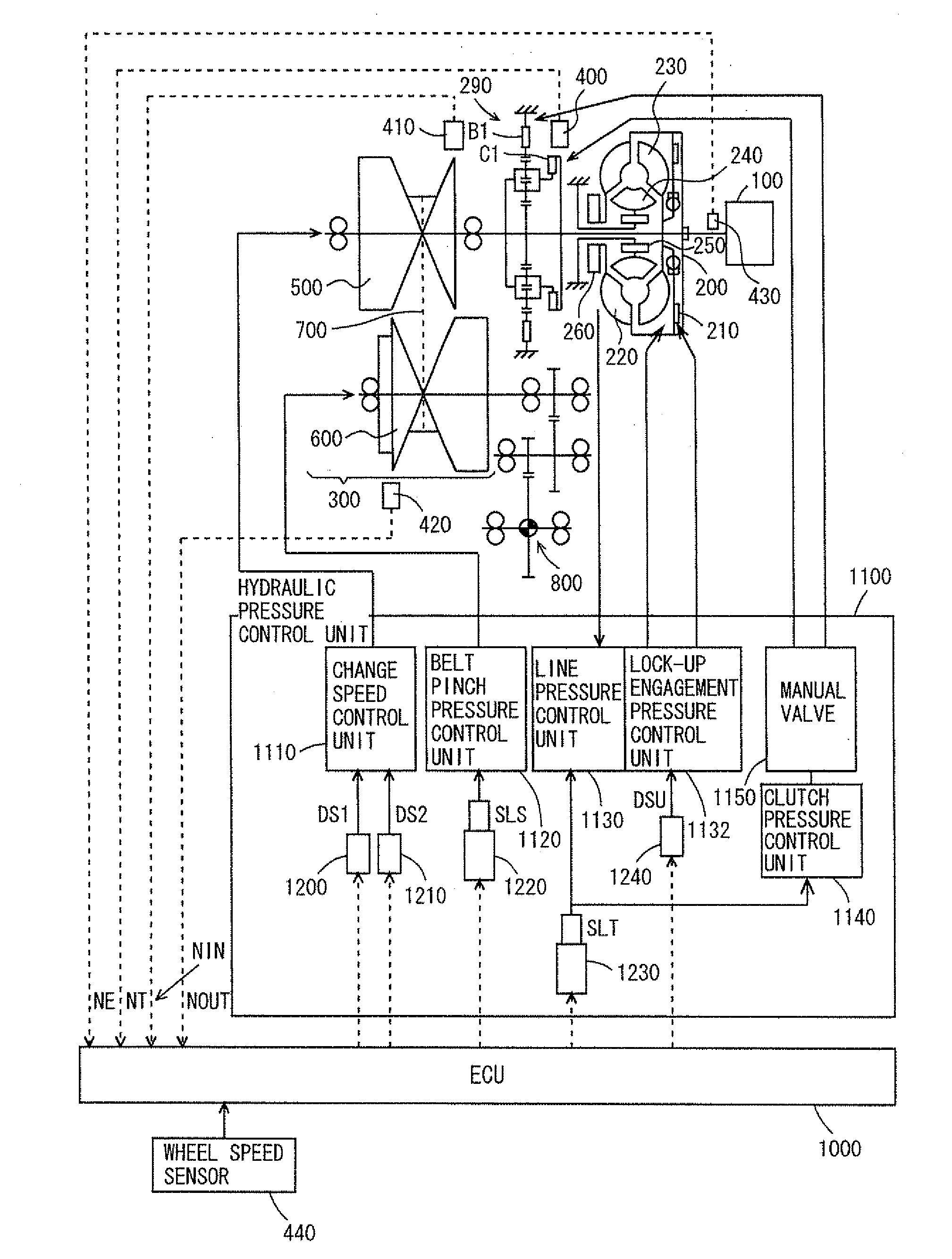
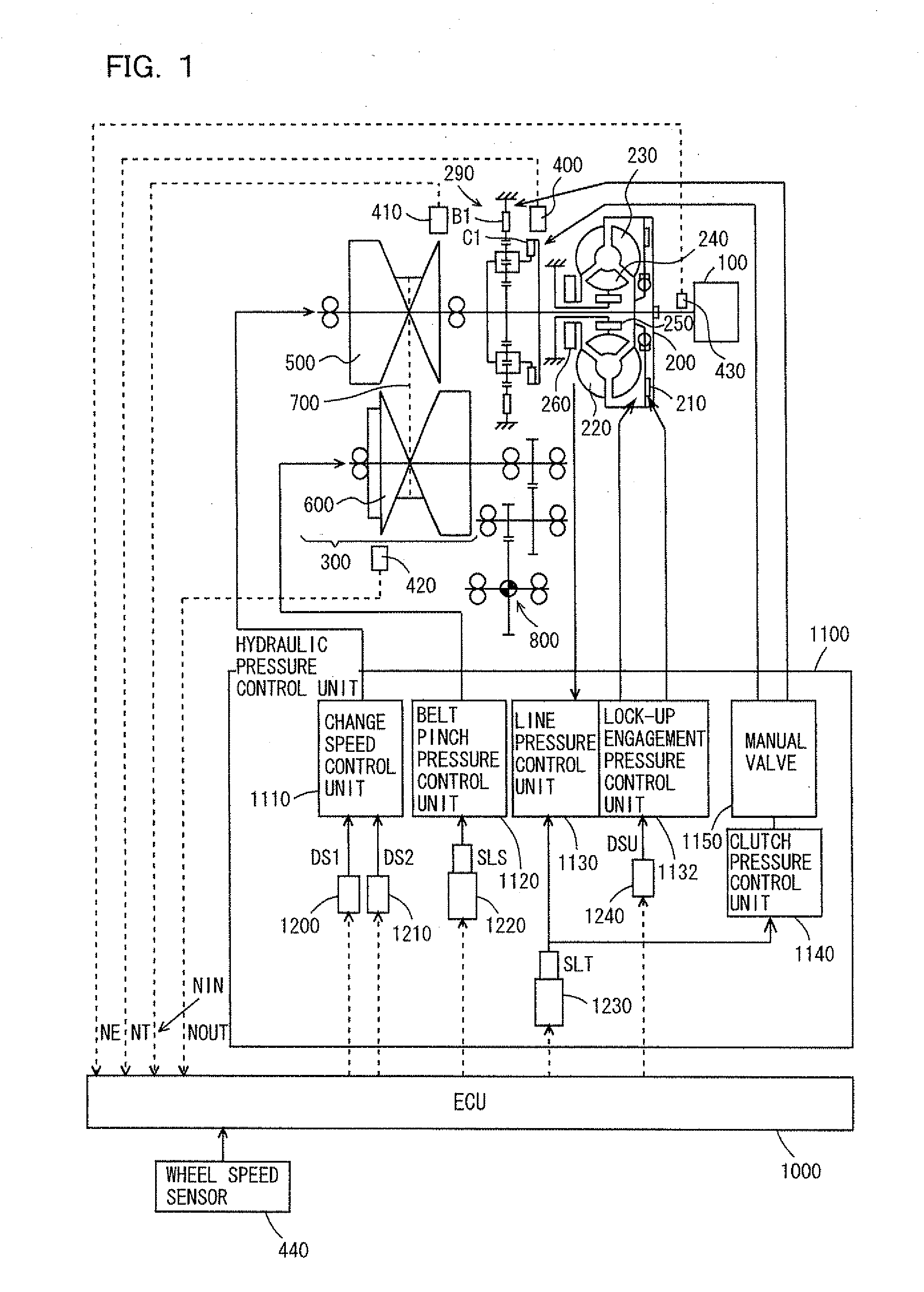
actuator of the driven pulley. This balance is adjusted by the first and second
regulator valves. For example, when the speed ratio at the time of start or the like is on the speed decease side, the hydraulic pressure supplied to the actuator of the drive pulley is lowered to reduce the winding
radius of the drive pulley, and then the hydraulic pressure will be increased to increase the winding
radius after the start of the vehicle. In this operation, the second
regulator valve regulates the hydraulic pressure supplied to the actuator of the driven pulley according to the hydraulic pressure supplied to the actuator of the drive pulley for suppressing occurrence of belt slip. Accordingly, in the operation of speed change toward the speed increase side in the first region, the winding radius cannot be increased when the first
regulator valve does not increase the hydraulic pressure supplied to the actuator of the drive pulley according to the running state, and therefore the speed change of the speed ratio cannot proceed. Therefore, the degree of change of the speed ratio lowers in the change operation of the speed ratio (e.g., a difference between the actual speed ratio and the target speed ratio increases). Thus, the occurrence of the
abnormality in the first regulator valve can be determined from the determination that the degree of following of the speed ratio in the change operation of the speed ratio is low. Conversely, when the hydraulic pressure supplied to the actuator of the driven pulley does not decrease in the second region on the speed increase side with respect to the first region, the hydraulic pressure supplied to the actuator of each pulley increases so that the winding radius cannot be changed. This results in a state that the difference between the actual speed ratio and the target speed ratio does not decrease. This lowers the degree of change of the actual speed ratio with respect to the target speed ratio in the change operation of the speed ratio. Thus, the occurrence of the
abnormality of the second regulator valve can be determined by determining that the degree of attaining the speed ratio is low in the change operation of the speed ratio. As described above, the fact that one of the first and second regulator valves is abnormal can be determined based on the degree of following of the speed ratio in the first region and the degree of attaining the speed ratio in the second region. Therefore, the location of the failure can be precisely specified. Accordingly, it is possible to provide the failure determining device and the failure determining method of the continuously variable transmission that can precisely specify the location of the failure when the change of the speed ratio becomes abnormal.
[0018]According to this invention, when the
physical quantity corresponding to the difference between the actual speed ratio and the target speed ratio (e.g., a difference in speed ratio or a difference in revolution speed of the drive pulley) is equal to or smaller than the predetermined value and the
physical quantity corresponding to the difference between the target speed ratio and the actual speed ratio is larger than a predetermined value, it is possible to determine that the actual speed ratio has not reached the speed ratio on the maximum speed-increase side. In this state, it is possible to determine that the hydraulic pressure supplied to the actuator of the driven pulley by the second regulator valve has not been decreased. Thus, it is possible to determine precisely that the second regulator valve is abnormal.
