[0007]Speaking with more particularity about the invention, and about what we see to be its remarkable, and experimentally demonstrated capability, it, the proposed “mattress
overlay”, has as its special purpose the dramatic minimization, and in many instances the complete prevention, of the onset and development of decubitus ulcers(sores)—medical conditions that lead to dangerous and potentially lethal injuries which come from long-term body-rest / support conditions. Accordingly, the overlay of the present invention is naturally, and particularly, well suited for placement on top of conventional, long-term, person / patient-support mattresses, such as hospital-
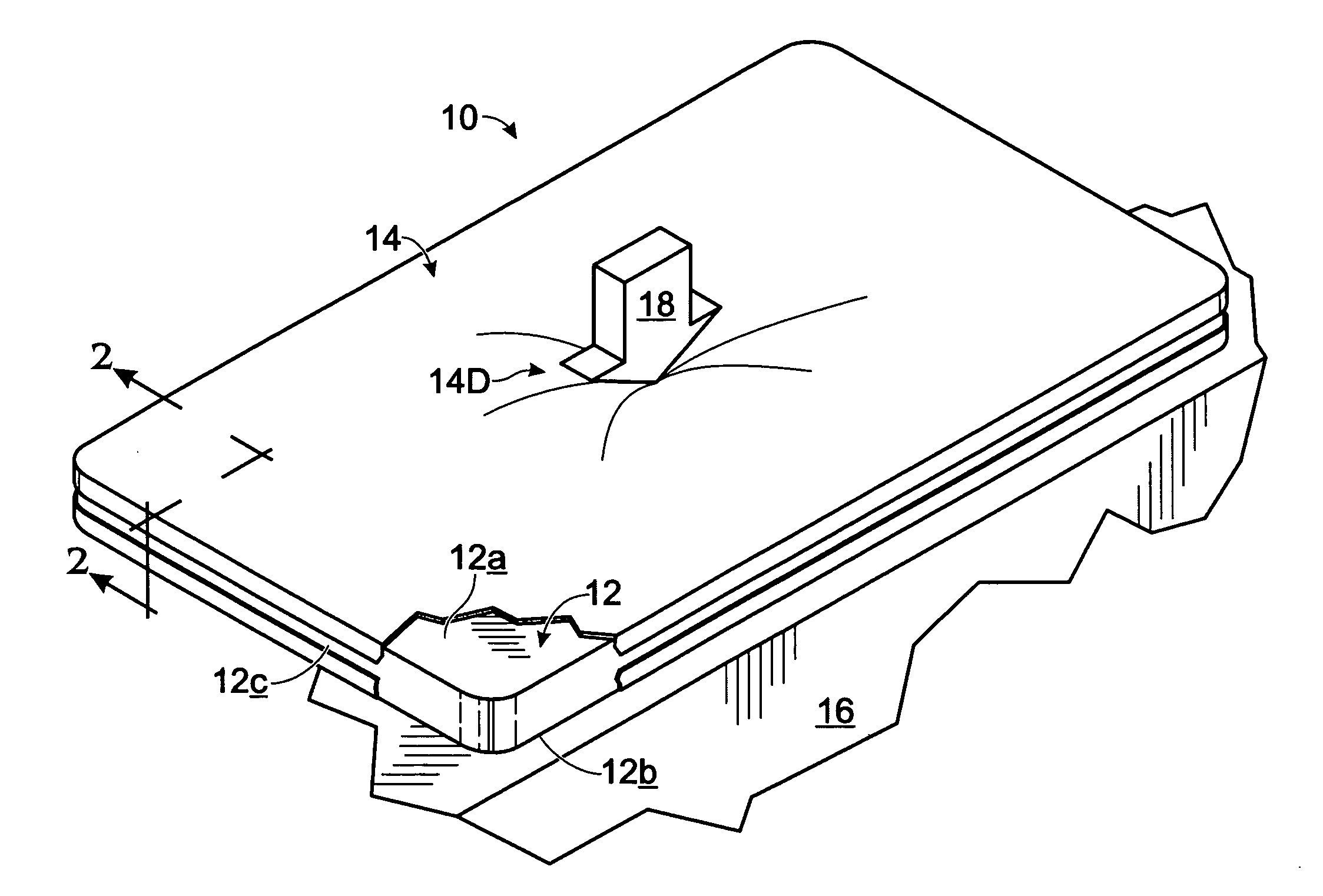
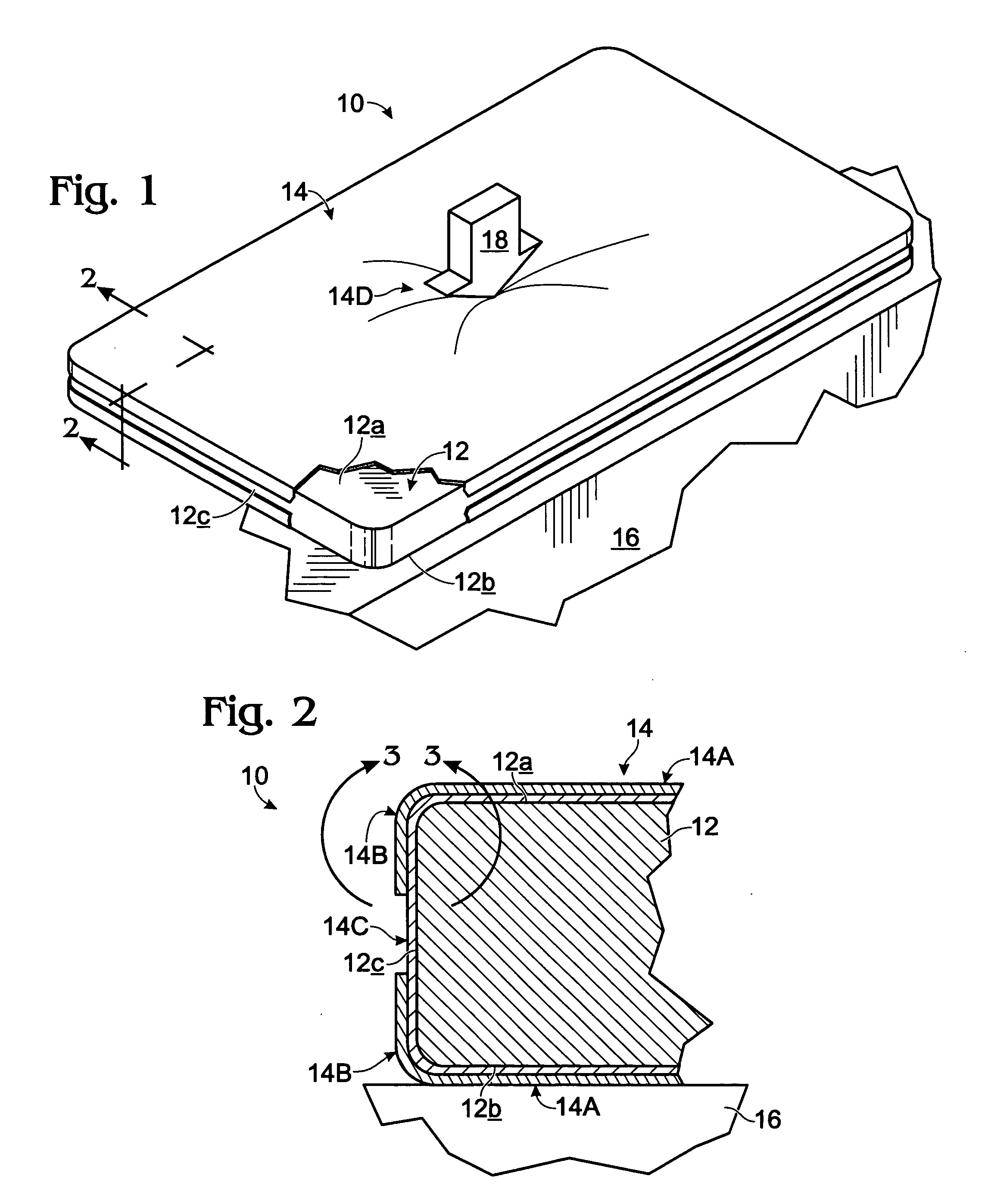
bed mattresses. While such a hospital-bed setting clearly presents an ideal use environment for the present invention, the defining term “mattress overlay” is intended herein to refer to any overlay structure constructed in accordance with the special and unique features of the present invention which may be shaped, sized, etc., for use not only on top of an underlying, conventional mattress structure, per se, but also in other similar environments where nonambulatory people, such as convalescing patients, may lie recurrently supported for long periods of time. The above-expressed concept of “direct”, underlying, person support, while it could (and can) include the concept of direct-to-
skin contact support, herein more typically means support which is furnished, for example, (a) “directly through” clothing (such pajamas, a
hospital gown, etc.), (b) through a bed sheet, or (c) through some combination of these and like things.
[0015](a) (1) avoiding even very short-term (minutes) of high, applied anatomical pressure, (2) at all times pressure-evenizing the contact-loading characteristics which define how the
anatomy of a bed-ridden patient is supported, and (3) specifically producing an anatomical loading condition, static and dynamic, whereby there exist substantially no notably high-pressure points (preferably none exceeding about 32-mm Hg, and even more preferably not exceeding about 20-mm Hg), and definitively no conditions involving a projecting portion of the person's
anatomy (i.e., a protuberance) bottoming out against either a non-yielding, or relatively non-yielding, underlying
support surface, or in any manner significantly raising (de-evenizing) anatomical
support pressure;
[0016](b) minimizing friction and shear engagement between the proposed overlay structure and a supported patient; and
[0017](c), very importantly, providing effective, ventilating, heat-removing airflow (more broadly, gas flow) in the region immediately beneath the contact-supported anatomy so as to avoid the development of hot-spots and overheating, and especially recognizing that those portion of a supported anatomy, such as bony prominences, which create notable, downward “indentations” in an underlying support structure should be offered proportionally larger access to air (gas) flow.
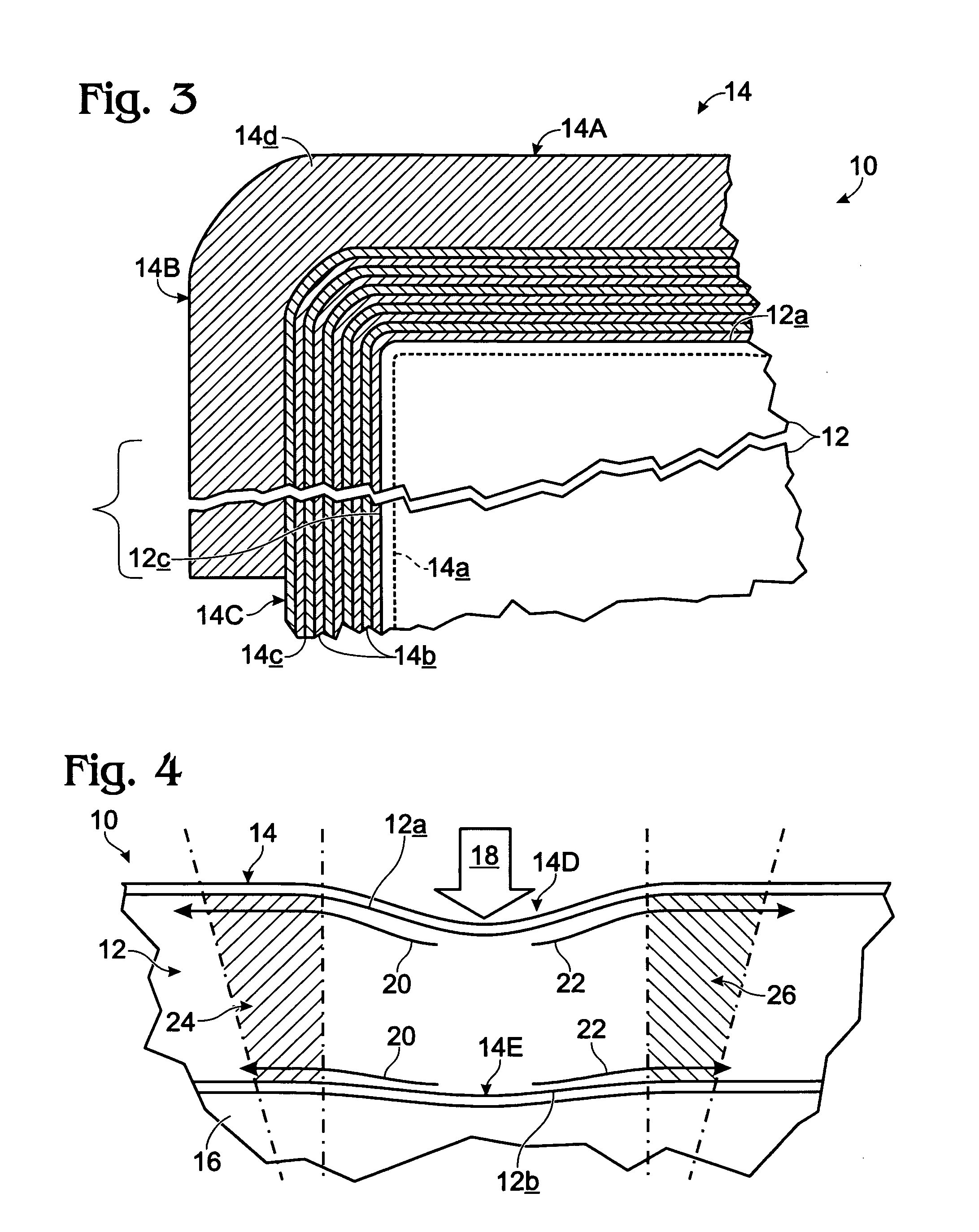
[0024]The just-mentioned, wet-interlayer sublayer joinder methodology (and arrangement) employed in relation to the preferred, ten, basic sublayers in the
coating produces, structurally, a final, cured, layered coating having, between substantially all next-adjacent, basic sublayers, and between the innermost, basic sublayer and the primer sublayer, what we refer to structurally herein as being finally cured, but initially wet, interfacial surfaces of joinder. We have found that this special type of wet, interfacial joinder structure enhances not only the gas-breathability characteristics of the overall coating, but also, importantly, the controlled shrinkage of the coating to produce the desired level of coating-internal tension, and core-expanse-internal compression. The one “area”, however, and as was just pointed out, of the prepared coating wherein the wet-interfacial joinder approach is not employed involves the application to each of the broad facial areas in the overlay of the final, eleventh coating sublayer.
[0029]From a methodologic general perspective, the invention involves a method for furnishing pressure-evenized, dynamic-reaction support for the anatomy including (a) supporting the anatomy with a 100%
open cell,
polyurethane, viscoelastic foam, and following such supporting, and within the supporting foam, reacting therein to both static and dynamic, anatomical-unevenness-produced indentations in the foam to expand and contract
foam cell-openness size, whereby deeper and sharper foam indentations result in greater cell-openness size.

