Guillotine cutter

Active Publication Date: 2010-08-05
BRADY WORLDWIDE INC
View PDF16 Cites 12 Cited by
  • Summary
  • Abstract
  • Description
  • Claims
  • Application Information

AI Technical Summary

Benefits of technology

[0014]In yet another form, the fixed blade has a coating applied thereto to reduce a coefficient of friction of the fixed blade.
[0024]Thus, an improved guillotine cutter is provided. This guillotine cutter includes a guillotine blade having a cutting motion that helps to urge the cut media from the exit chute of the cutter. This reduces the likelihood of the cut media being pulled into the frame of the cutter, requiring that the user fish the cut media out. Further, the guillotine cutter provides a frame having integrated bearing surfaces for supporting many of the movable components of the cutter. This minimizes the complexity of the assembly of the cutter, reducing the number of parts (e.g., by elimination of separate bushings and other such additional components) and the time required to assemble the cutter. This ultimately reduces the cost of producing the cutter.

Problems solved by technology

Unfortunately, cutting adhesive-backed media is particularly irksome, as the adhesive of the media tends to builds up on the blades over time.
This adhesive build-up on the blades degrades the quality of the cut over the life of the blades.
The adhesive build-up on the blades may also cause the cut media to stick to the cutting edge.
In a guillotine-style cutter, this sticking may result in the media not properly feeding from the exit chute, as the portion of the media severed by the cutting edge may continue to travel with the cutting edge even after the media is cut.
Correcting this problem may require user intervention to retrieve any media that has not exited the cutter.
Further, although straightforward in function, cutters typically include complex assemblies with numerous parts.
Having a complicated assembly adds cost to the cutter, increases the production time of the cutter, and adds complexity to the cutter.

Method used


Image

  • Guillotine cutter
  • Guillotine cutter
  • Guillotine cutter

Examples


Embodiment Construction

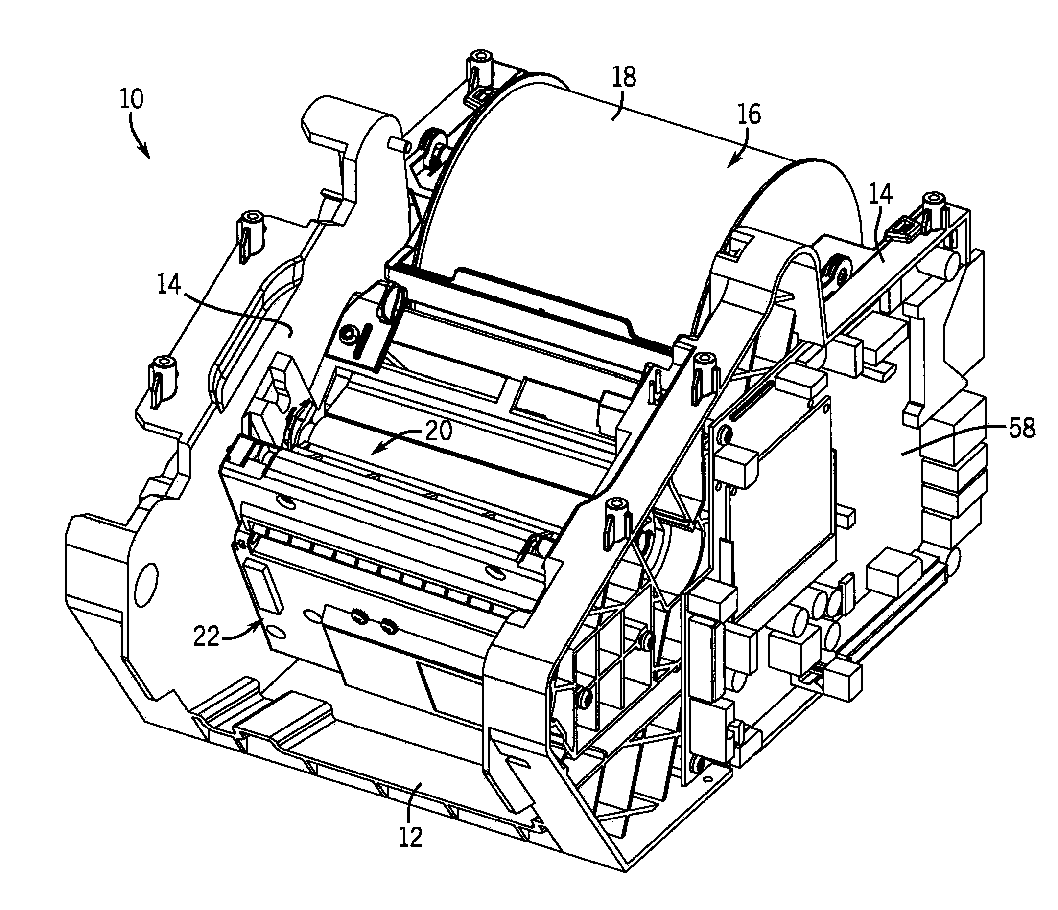
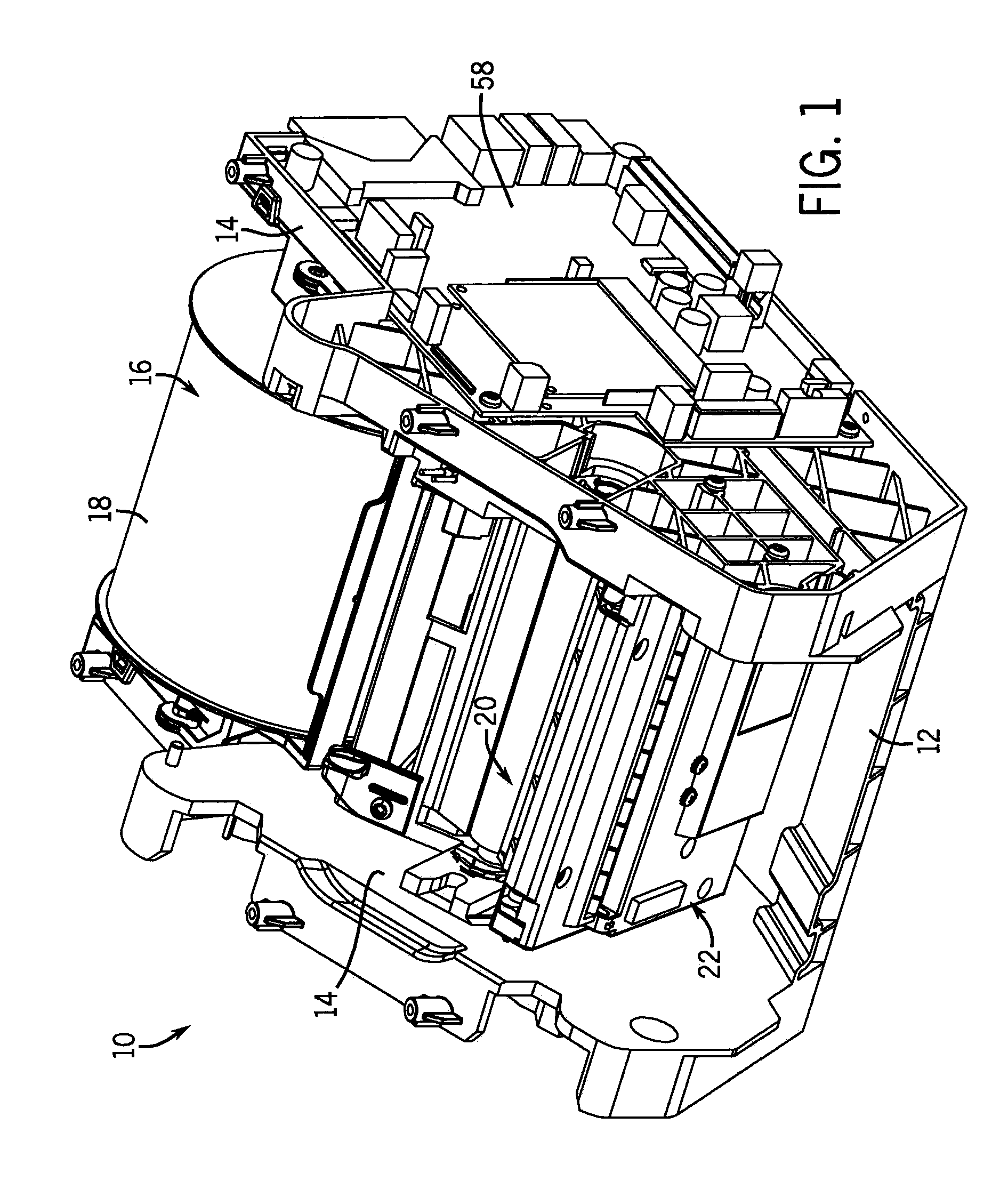
[0034]Referring first to FIG. 1, a carriage 10 for insertion in a printer is illustrated. The carriage 10 has a horizontal base wall 12 with two side walls 14 vertically extending therefrom to form a U-shaped cradle. The two side walls 14 have surfaces facing one another that include features formed thereon (e.g., slots or the like) to allow the carriage 10 to support a roll 16 having media 18 wrapped thereabout, a print head assembly 20, and a guillotine cutter 22. Most of the components supported by the carriage 10 are designed to be removed for periodic maintenance and / or for replacement after they are consumed. For example, the guillotine cutter 22 is a modular component that is removeably inserted into the carriage 10.

[0035]In general operation, the printer works as follows. Using various rollers and guides, the media 18 is fed from the roll 16 and past a print head (not shown) in the print head assembly 20. The print head prints text, an image, a barcode, or the like onto the ...


PUM

PropertyMeasurementUnit
Angleaaaaaaaaaa
Frictionaaaaaaaaaa

Abstract

An improved guillotine cutter for a printer is disclosed. The guillotine cutter includes a guillotine blade having a cutting motion that helps to urge the cut media from the exit chute of the frame. This reduces the likelihood of the cut media becoming pulled into the frame of the cutter, requiring that the user fish the cut media out. The guillotine cutter further provides a frame having integrated bearing surfaces for supporting many of the movable components of the cutter. This minimizes the complexity of the assembly of the cutter, reducing the number of parts (by elimination of separate bearings and other such additional components) and time required to assemble the cutter.

Description

CROSS-REFERENCE TO RELATED APPLICATION[0001]Not applicable.STATEMENT OF FEDERALLY SPONSORED RESEARCH OR DEVELOPMENT[0002]Not applicable.BACKGROUND OF THE INVENTION[0003]This invention generally relates to printers. In particular, this invention relates to a guillotine cutter for a printer.[0004]Many printers print onto continuous rolls of media. As the media extends through the printer, the media typically is pulled off of a roll, fed past a print head, and fed through an exit chute on the printer. As the media is continuous as it is pulled from the roll, it occasionally needs to be cut to separate the printed portion from the rest of the roll. To sever the media from the roll, a cutter may be placed near the exit chute and actuated to cut the media.[0005]In one type of cutter, a guillotine cutter, the media is fed through an opening between two blades. When the guillotine cutter is actuated to cut the media, one of the blades is moved past the other blade in a direction that is gen...

Claims


Application Information

Patent Timeline
IPC IPC(8): B26D1/01B26D7/00
CPCB26D1/085B26D1/565B26D7/1818B26D7/088B26D5/14Y10T83/2096Y10T83/9447Y10T83/9454Y10T83/95
Inventor FLOOD, BRIANANDERSON, KERRY
Owner BRADY WORLDWIDE INC
Why Eureka
Try Eureka