Deposition of materials with low ductility using solid free-form fabrication

a technology of free-form fabrication and low ductility, which is applied in the direction of manufacturing tools, welding/cutting media/materials, and manufacturing tools. it can solve the problems of low ductility, brittleness, and material fracture, and achieves low ductility and low ductility. , the effect of minimizing the occurrence of material stresses

Inactive Publication Date: 2010-08-05
HONEYWELL INT INC
View PDF21 Cites 75 Cited by
  • Summary
  • Abstract
  • Description
  • Claims
  • Application Information

AI Technical Summary

Benefits of technology

[0009]In one embodiment, and by way of example only the method includes the steps of: (a) providing an energy beam configured to emit at least one of a variable magnitude energy beam or a constant magnitude energy beam; (b) preheating a substrate onto which the successive layers of feedstock material with low ductility will be deposited by directing the energy beam to a predetermined targeted region; (c) introducing the feedstock material with low ductility into the energy beam to produce a pool of molten feedstock in the predetermined targeted region; and (d) adjusting the energy beam to provide a cool down phase where the pool of molten feedstock solidifies at a predetermined elevated temperature that minimizes the occurrence of material stresses.
[0010]In another exemplary embodiment, and by way of example only the present invention also provides a solid free form fabrication method for manufacturing a component from successive layers of feedstock material with low ductility, with each of the successive layers representing a cross-sectional component slice, the method including the steps of: (a) creating a plasma stream by energizing a flowing gas using an arc electrode, the arc electrode having a variable magnitude current supplied thereto; (b) preheating a substrate onto which the successive layers of feedstock material with low ductility will be deposited by providing a first current amperage and directing the plasma stream to a predetermined targeted region; (c) adjusting the variable magnitude current supplied to the arc electrode by providing an increase in current amperage toward a second current amperage and directing the plasma stream to the predetermined targeted region; (d) introducing the feedstock material with low ductility into the plasma stream to produce a pool of molten feedstock in the predetermined targeted region; and (e) adjusting the variable magnitude current supplied to the arc electrode by providing a decrease in current amperage toward the first current amperage, thus providing a cool down phase where the pool of molten feedstock solidifies at a predetermined elevated temperature that minimizes the occurrence of material stresses.

Problems solved by technology

Fabrication using these low ductile, or brittle, materials can be very difficult as the low ductility can result in fabrication stresses in the material that may result in fractures.
In conventional fabrication methods such as castings, thermal gradients may occur during cooling of the material and result in stress gradients that are sometimes severe.
Likewise, when machining these materials fractures can occur due to induced strains that exceed the maximum, but low, elongations.
When fabricating using typical solid free-form fabrication (SFF) processes, similar to additive manufacturing, significant thermal gradients are induced and stress gradients result which can induce fracture in materials, such as materials with low ductility.
In effect, SFF processes may result in more severe thermal and stress gradients than conventional processes due to the inherent high thermal gradient required in SFF processes since a local spot is at its melting point and the same part at some distant area may be at a much lower temperature perhaps even at room temperature.
One inherent challenge when building a component using materials with low ductility, such as those previously identified, and SFF processes is in minimizing the occurrence of thermal gradients and resulting stress gradients that often lead to fractures.

Method used


Image

  • Deposition of materials with low ductility using solid free-form fabrication
  • Deposition of materials with low ductility using solid free-form fabrication
  • Deposition of materials with low ductility using solid free-form fabrication

Examples


Embodiment Construction

[0016]The following detailed description of the invention is merely exemplary in nature and is not intended to limit the invention or the application and uses of the invention. Furthermore, there is no intention to be bound by any theory presented in the preceding background of the invention or the following detailed description of the invention.

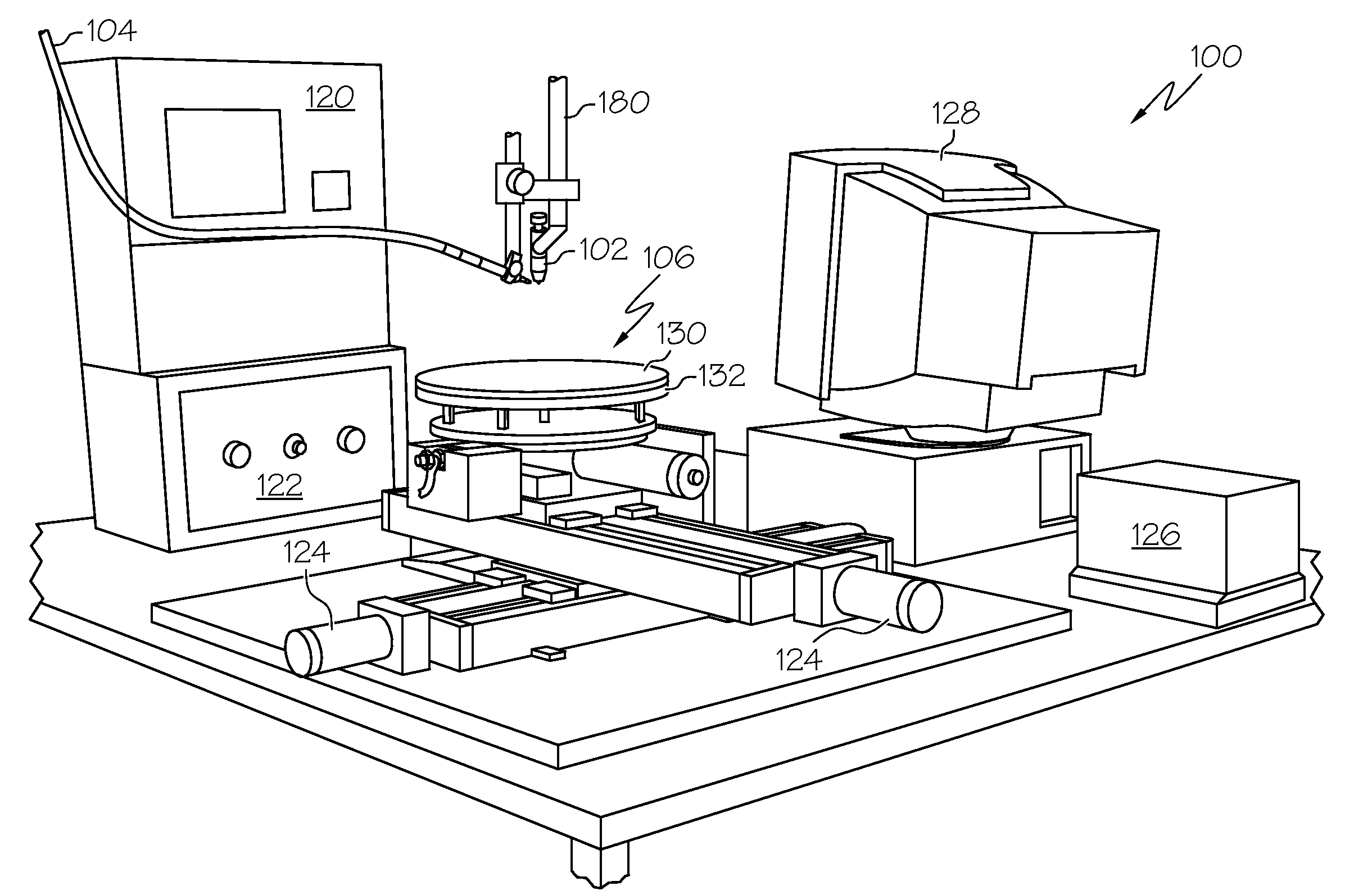
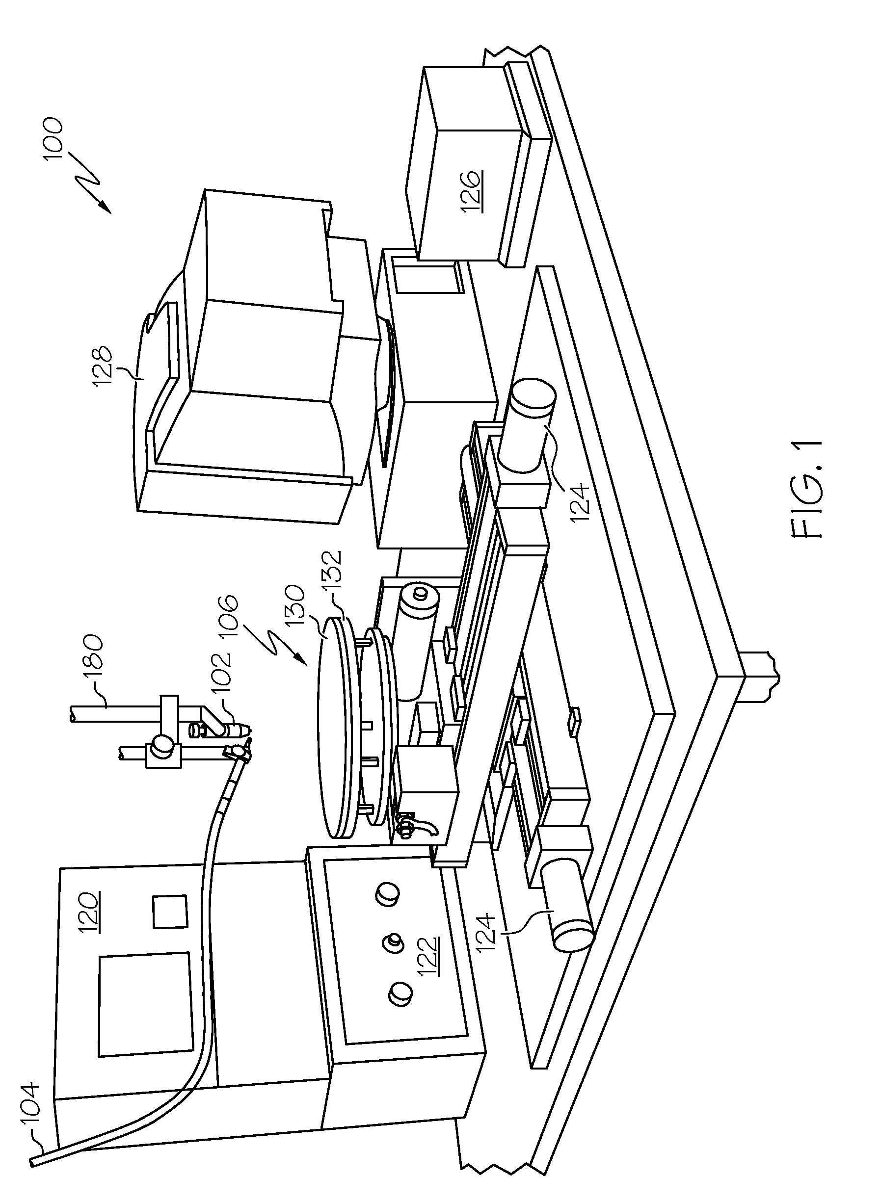
[0017]FIG. 1 is a perspective view of a SFF system, and more particularly an IFF system 100, which includes a heating torch 102 that functions in cooperation with a wire feed mechanism 104 and a positioning system 106 to build up a workpiece in a continuous or layer-by-layer manner. The positioning system 106 continuously positions and repositions the workpiece in a manner whereby feedstock material may be added to it through the wire feed mechanism 104 at predetermined deposition points. Further, the positioning system 106 may also be configured to coordinate movement and control of the torch 102 and the wire feed mechanism 104 together wit...


PUM

PropertyMeasurementUnit
elongationsaaaaaaaaaa
temperatureaaaaaaaaaa
ductilityaaaaaaaaaa

Abstract

A solid free-form (SFF) method is used to manufacture a component from successive layers of feedstock material with low ductility. A plasma stream is created by energizing a flowing gas using an arc electrode, the arc electrode having a variable magnitude current supplied thereto. The plasma stream is directed to a predetermined targeted region to preheat the predetermined targeted region prior to deposition. The current is adjusted and the feedstock material is introduced into the plasma stream to deposit molten feedstock in the predetermined targeted region. The current is adjusted and the molten feedstock is slowly cooled at an elevated temperature, typically above the brittle to ductile transition temperature of the feedstock material, in a cooling phase to minimize the occurrence of material stresses.

Description

TECHNICAL FIELD[0001]The present invention relates to the fabrication of parts and devices from materials having low ductility, and more particularly relates to solid free-form fabrication processes that create parts and devices from materials having low ductility by selectively applying feedstock material to a substrate or an in-process workpiece.BACKGROUND[0002]Materials having low ductility are brittle at room temperature, sometimes severely so with elongations of less than 1%. Materials included in this class have a high brittle to ductile transition temperature. Metals having these properties include pure metals, such as tungsten and molybdenum, and their alloys and other alloys such as cast irons, intermetallic compounds, ceramics and plastics. Fabrication using these low ductile, or brittle, materials can be very difficult as the low ductility can result in fabrication stresses in the material that may result in fractures. In conventional fabrication methods such as castings,...

Claims


Application Information

Patent Timeline
Patent Type & Authority Applications(United States)
IPC IPC(8): B23K15/00B23K9/00
CPCB23K9/04B23K35/383B23K9/23B23K10/006B23K10/027B23K15/0086B23K15/0093B23K26/063B23K26/3206B23K26/322B23K26/3273B23K26/3246B23K26/345B23K35/0227B23K35/0261B23K35/38B23K9/09B23K26/32B23K26/324B23K26/342B23K26/0622B23K2103/06B23K2103/08B23K2103/42B23K2103/50B23K2103/52B33Y10/00B33Y40/00B33Y40/10
Inventor ADAMS, ROBBIE JOSEPH
Owner HONEYWELL INT INC
Why Eureka
Try Eureka